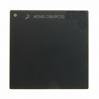
MC68EC060RC50 Freescale Semiconductor, MC68EC060RC50 Datasheet - Page 294

MC68EC060RC50
Manufacturer Part Number
MC68EC060RC50
Description
IC MPU 32BIT 50MHZ 206-PGA
Manufacturer
Freescale Semiconductor
Specifications of MC68EC060RC50
Processor Type
M680x0 32-Bit
Speed
50MHz
Voltage
3.3V
Mounting Type
Surface Mount
Package / Case
206-PGA
Family Name
M68000
Device Core
ColdFire
Device Core Size
32b
Frequency (max)
50MHz
Instruction Set Architecture
RISC
Supply Voltage 1 (typ)
3.3V
Operating Supply Voltage (max)
3.465V
Operating Supply Voltage (min)
3.135V
Operating Temp Range
0C to 110C
Operating Temperature Classification
Commercial
Mounting
Through Hole
Pin Count
206
Package Type
PGA
Lead Free Status / RoHS Status
Contains lead / RoHS non-compliant
Features
-
Lead Free Status / Rohs Status
Compliant
Available stocks
Company
Part Number
Manufacturer
Quantity
Price
Company:
Part Number:
MC68EC060RC50
Manufacturer:
NXP
Quantity:
1 746
- Current page: 294 of 416
- Download datasheet (2Mb)
IEEE 1149.1 Test (JTAG) and Debug Pipe Control Modes
interrupts). The 32-bit instruction address of the first instruction of the emulator interrupt
exception handler is derived as with other exceptions—the memory contents of address
VBR + exception offset ($30).
The emulator mode entry from the breakpoint exception shares the same vector table entry
(VBR + $30) as the emulator interrupt exception. However, the emulator mode entry from
the breakpoint exception requires that the exception handler increment the stacked PC by
two to point to the instruction following the breakpoint instruction. On the other hand, the
emulator interrupt stack’s PC already points to the next instruction.
9.3 SWITCHING BETWEEN JTAG AND DEBUG PIPE CONTROL
MODES OF OPERATION
Since JTAG and the debug pipe control modes share the same set of pins, only one mode
can be used at a time. Normally, the JTAG mode is used only during product testing, and
the debug pipe control mode is used by the end user in conjunction with an in-circuit emu-
lator. For this use, the board manufacturer normally designs in whatever JTAG functionality
is required without regard to whether the board will eventually be used in the debug pipe
control mode or not. The responsibility of allowing the processor to operate under the debug
pipe control mode lies with the emulator vendor. The emulator vendor needs to ensure that
the socket built to carry the processor has the target system’s JTAG pins isolated from the
processor to allow full control of these pins. Hence, under normal circumstances, dynamic
switching between JTAG and debug pipe control modes is unnecessary.
However, for systems that need to switch between these modes can do so by following
some guidelines. These guidelines are illustrated in Figure 9-12 and Figure 9-13. These fig-
ures illustrate how to transition between the JTAG mode and the debug pipe control mode.
MOTOROLA
M68060 USER’S MANUAL
9-33
Related parts for MC68EC060RC50
Image
Part Number
Description
Manufacturer
Datasheet
Request
R
Part Number:
Description:
Manufacturer:
Freescale Semiconductor, Inc
Datasheet:
Part Number:
Description:
Manufacturer:
Freescale Semiconductor, Inc
Datasheet:
Part Number:
Description:
Manufacturer:
Freescale Semiconductor, Inc
Datasheet:
Part Number:
Description:
Manufacturer:
Freescale Semiconductor, Inc
Datasheet:
Part Number:
Description:
Manufacturer:
Freescale Semiconductor, Inc
Datasheet:
Part Number:
Description:
Manufacturer:
Freescale Semiconductor, Inc
Datasheet:
Part Number:
Description:
Manufacturer:
Freescale Semiconductor, Inc
Datasheet:
Part Number:
Description:
Manufacturer:
Freescale Semiconductor, Inc
Datasheet:
Part Number:
Description:
Manufacturer:
Freescale Semiconductor, Inc
Datasheet:
Part Number:
Description:
Manufacturer:
Freescale Semiconductor, Inc
Datasheet:
Part Number:
Description:
Manufacturer:
Freescale Semiconductor, Inc
Datasheet:
Part Number:
Description:
Manufacturer:
Freescale Semiconductor, Inc
Datasheet:
Part Number:
Description:
Manufacturer:
Freescale Semiconductor, Inc
Datasheet:
Part Number:
Description:
Manufacturer:
Freescale Semiconductor, Inc
Datasheet:
Part Number:
Description:
Manufacturer:
Freescale Semiconductor, Inc
Datasheet:


