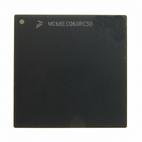
MC68EC060RC50 Freescale Semiconductor, MC68EC060RC50 Datasheet - Page 292

MC68EC060RC50
Manufacturer Part Number
MC68EC060RC50
Description
IC MPU 32BIT 50MHZ 206-PGA
Manufacturer
Freescale Semiconductor
Specifications of MC68EC060RC50
Processor Type
M680x0 32-Bit
Speed
50MHz
Voltage
3.3V
Mounting Type
Surface Mount
Package / Case
206-PGA
Family Name
M68000
Device Core
ColdFire
Device Core Size
32b
Frequency (max)
50MHz
Instruction Set Architecture
RISC
Supply Voltage 1 (typ)
3.3V
Operating Supply Voltage (max)
3.465V
Operating Supply Voltage (min)
3.135V
Operating Temp Range
0C to 110C
Operating Temperature Classification
Commercial
Mounting
Through Hole
Pin Count
206
Package Type
PGA
Lead Free Status / RoHS Status
Contains lead / RoHS non-compliant
Features
-
Lead Free Status / Rohs Status
Compliant
Available stocks
Company
Part Number
Manufacturer
Quantity
Price
Company:
Part Number:
MC68EC060RC50
Manufacturer:
NXP
Quantity:
1 746
- Current page: 292 of 416
- Download datasheet (2Mb)
inserting the commands to guarantee that there is sufficient time between commands to
allow for proper operation.
Commands $0D three-states all outputs and causes all inputs to be ignored. Command $0E
allows outputs to be driven and inputs to be sampled.
Commands $10–$17 force specific processor features to be disabled. Command $0F
negates the effects of all the commands between $10 and $17. These commands override
the configuration as defined by the CACR, PCR, or TCR. Note that these instructions affect-
ing processor configuration do not affect the operation of the MOVEC instructions which
affect the CACR, PCR, or TCR. The MOVEC instruction to these registers operates nor-
mally, but the enabling of a specific feature is overridden if the corresponding debug function
has been executed. Any MOVEC reading contents of the CACR, PCR, or TCR will return
the value contained in the register and is independent of any debug commands which may
have been executed.
Commands $18–$1B configure whether or not the trace and breakpoint exceptions force a
processor entry into emulator mode.
Commands $1C–$1F generate an emulator interrupt exception.
9.2.3 Emulator Mode
The MC68060 implements a mode of operation that provides an outside control function
(i.e., emulator) controllability and visibility mechanisms to direct MC68060 processor oper-
ations.
When the processor is in the emulator mode, the branch cache is not used. Instructions exe-
cuted when the MC68060 is in emulator mode generate address space and bus transfer
cycle attributes as an alternate logical function code space access with no address transla-
tion:
Entry into emulator mode can be accomplished via one of four methods:
MOTOROLA
• No address translation
• No cache access
• TT1, TT0 = 2 {Alternate Logical Function Code Access}
• TM2–TT0 = 5 (operand references) or 6 (instruction references) {Logical Function Code
1. A “generate emulator interrupt” command can be initiated through the debug pipe con-
5 or 6}.
trol mode. If this command is received by the MC68060, the processor waits for an
interruptible point in the instruction stream, and then generates an emulator interrupt
exception. A four-word exception stack frame (in alternate address space) is created,
with the PC value equal to the next PC and the exception type/vector offset equal to
$30. The vector pointed to by VBR + $30 defines the exception handler entry point,
within the alternate address space (TT = 2, TM = 6).
M68060 USER’S MANUAL
IEEE 1149.1 Test (JTAG) and Debug Pipe Control Modes
9-31
Related parts for MC68EC060RC50
Image
Part Number
Description
Manufacturer
Datasheet
Request
R
Part Number:
Description:
Manufacturer:
Freescale Semiconductor, Inc
Datasheet:
Part Number:
Description:
Manufacturer:
Freescale Semiconductor, Inc
Datasheet:
Part Number:
Description:
Manufacturer:
Freescale Semiconductor, Inc
Datasheet:
Part Number:
Description:
Manufacturer:
Freescale Semiconductor, Inc
Datasheet:
Part Number:
Description:
Manufacturer:
Freescale Semiconductor, Inc
Datasheet:
Part Number:
Description:
Manufacturer:
Freescale Semiconductor, Inc
Datasheet:
Part Number:
Description:
Manufacturer:
Freescale Semiconductor, Inc
Datasheet:
Part Number:
Description:
Manufacturer:
Freescale Semiconductor, Inc
Datasheet:
Part Number:
Description:
Manufacturer:
Freescale Semiconductor, Inc
Datasheet:
Part Number:
Description:
Manufacturer:
Freescale Semiconductor, Inc
Datasheet:
Part Number:
Description:
Manufacturer:
Freescale Semiconductor, Inc
Datasheet:
Part Number:
Description:
Manufacturer:
Freescale Semiconductor, Inc
Datasheet:
Part Number:
Description:
Manufacturer:
Freescale Semiconductor, Inc
Datasheet:
Part Number:
Description:
Manufacturer:
Freescale Semiconductor, Inc
Datasheet:
Part Number:
Description:
Manufacturer:
Freescale Semiconductor, Inc
Datasheet:


