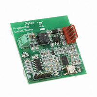
MCP1631RD-DCPC1 Microchip Technology, MCP1631RD-DCPC1 Datasheet - Page 13

MCP1631RD-DCPC1
Manufacturer Part Number
MCP1631RD-DCPC1
Description
REF DES BATT CHARG OR LED DRIVER
Manufacturer
Microchip Technology
Datasheets
1.PIC16F616T-ISL.pdf
(214 pages)
2.MCP1631VHVT-330EST.pdf
(34 pages)
3.MCP1631VHVT-330EST.pdf
(32 pages)
Specifications of MCP1631RD-DCPC1
Current - Output / Channel
700mA
Outputs And Type
1, Non-Isolated
Features
Firmware for Li-Ion, NiMH, and NiCd Battery Charger
Voltage - Input
3.5 ~ 16 V
Utilized Ic / Part
MCP1631HV, PIC16F616
Core Chip
MCP1631HV, PIC16F616
Topology
Parallel, Series
Output Current
1A
No. Of Outputs
1
Input Voltage
3.5V To 16V
Dimming Control Type
Analog
Kit Contents
Board
Lead Free Status / RoHS Status
Lead free / RoHS Compliant
Voltage - Output
-
Lead Free Status / Rohs Status
Lead free / RoHS Compliant
- PIC16F616T-ISL PDF datasheet
- MCP1631VHVT-330EST PDF datasheet #2
- MCP1631VHVT-330EST PDF datasheet #3
- Current page: 13 of 214
- Download datasheet (4Mb)
2.0
2.1
The
program counter capable of addressing an 8K x 14
program memory space. Only the first 1K x 14
(0000h-3FF) for the PIC16F610/16HV610 and the first
2K x 14 (0000h-07FFh) for the PIC16F616/16HV616 is
physically implemented. Accessing a location above
these boundaries will cause a wraparound within the
first 1K x 14 space (PIC16F610/16HV610) and 2K x 14
space (PIC16F616/16HV616). The Reset vector is at
0000h and the interrupt vector is at 0004h (see
Figure 2-1).
FIGURE 2-1:
© 2009 Microchip Technology Inc.
CALL, RETURN
RETFIE, RETLW
PIC16F610/616/16HV610/616
MEMORY ORGANIZATION
Program Memory Organization
On-chip Program
Interrupt Vector
Stack Level 1
Stack Level 2
Stack Level 8
Reset Vector
PC<12:0>
Memory
PROGRAM MEMORY MAP
AND STACK FOR THE
PIC16F610/16HV610
13
has a
0000h
0004h
0005h
03FFh
0400h
1FFFh
PIC16F610/616/16HV610/616
13-bit
FIGURE 2-2:
CALL, RETURN
RETFIE, RETLW
On-chip Program
Interrupt Vector
Stack Level 1
Stack Level 2
Stack Level 8
Reset Vector
PC<12:0>
Memory
PROGRAM MEMORY MAP
AND STACK FOR THE
PIC16F616/16HV616
13
DS41288F-page 13
0000h
0004h
0005h
07FFh
0800h
1FFFh
Related parts for MCP1631RD-DCPC1
Image
Part Number
Description
Manufacturer
Datasheet
Request
R

Part Number:
Description:
REFERENCE DESIGN MCP1631HV
Manufacturer:
Microchip Technology
Datasheet:

Part Number:
Description:
REFERENCE DESIGN FOR MCP1631HV
Manufacturer:
Microchip Technology
Datasheet:

Part Number:
Description:
Manufacturer:
Microchip Technology Inc.
Datasheet:

Part Number:
Description:
Manufacturer:
Microchip Technology Inc.
Datasheet:

Part Number:
Description:
Manufacturer:
Microchip Technology Inc.
Datasheet:

Part Number:
Description:
Manufacturer:
Microchip Technology Inc.
Datasheet:

Part Number:
Description:
Manufacturer:
Microchip Technology Inc.
Datasheet:

Part Number:
Description:
Manufacturer:
Microchip Technology Inc.
Datasheet:

Part Number:
Description:
Manufacturer:
Microchip Technology Inc.
Datasheet:

Part Number:
Description:
Manufacturer:
Microchip Technology Inc.
Datasheet:


