MCP1631RD-DCPC1 Microchip Technology, MCP1631RD-DCPC1 Datasheet - Page 132
MCP1631RD-DCPC1
Manufacturer Part Number
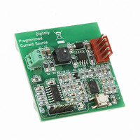
MCP1631RD-DCPC1
Description
REF DES BATT CHARG OR LED DRIVER
Manufacturer
Microchip Technology
Datasheets
1.PIC16F616T-ISL.pdf
(214 pages)
2.MCP1631VHVT-330EST.pdf
(34 pages)
3.MCP1631VHVT-330EST.pdf
(32 pages)
Specifications of MCP1631RD-DCPC1
Current - Output / Channel
700mA
Outputs And Type
1, Non-Isolated
Features
Firmware for Li-Ion, NiMH, and NiCd Battery Charger
Voltage - Input
3.5 ~ 16 V
Utilized Ic / Part
MCP1631HV, PIC16F616
Core Chip
MCP1631HV, PIC16F616
Topology
Parallel, Series
Output Current
1A
No. Of Outputs
1
Input Voltage
3.5V To 16V
Dimming Control Type
Analog
Kit Contents
Board
Lead Free Status / RoHS Status
Lead free / RoHS Compliant
Voltage - Output
-
Lead Free Status / Rohs Status
Lead free / RoHS Compliant


PIC16F610/616/16HV610/616
BTFSS
Syntax:
Operands:
Operation:
Status Affected:
Description:
CALL
Syntax:
Operands:
Operation:
Status Affected:
Description:
CLRF
Syntax:
Operands:
Operation:
Status Affected:
Description:
CLRW
Syntax:
Operands:
Operation:
Status Affected:
Description:
DS41288F-page 132
Bit Test f, Skip if Set
[ label ] BTFSS f,b
0 ≤ f ≤ 127
0 ≤ b < 7
skip if (f<b>) = 1
None
If bit ‘b’ in register ‘f’ is ‘0’, the next
instruction is executed.
If bit ‘b’ is ‘1’, then the next
instruction is discarded and a NOP
is executed instead, making this a
two-cycle instruction.
Call Subroutine
[ label ] CALL k
0 ≤ k ≤ 2047
(PC)+ 1→ TOS,
k → PC<10:0>,
(PCLATH<4:3>) → PC<12:11>
None
Call Subroutine. First, return
address (PC + 1) is pushed onto
the stack. The eleven-bit
immediate address is loaded into
PC bits <10:0>. The upper bits of
the PC are loaded from PCLATH.
CALL is a two-cycle instruction.
Clear W
[ label ] CLRW
None
00h → (W)
1 → Z
Z
W register is cleared. Zero bit (Z)
is set.
Clear f
[ label ] CLRF
0 ≤ f ≤ 127
00h → (f)
1 → Z
Z
The contents of register ‘f’ are
cleared and the Z bit is set.
f
CLRWDT
Syntax:
Operands:
Operation:
Status Affected:
Description:
COMF
Syntax:
Operands:
Operation:
Status Affected:
Description:
DECF
Syntax:
Operands:
Operation:
Status Affected:
Description:
Complement f
(f) → (destination)
Z
TO, PD
[ label ] COMF
0 ≤ f ≤ 127
d ∈ [0,1]
The contents of register ‘f’ are
complemented. If ‘d’ is ‘0’, the
result is stored in W. If ‘d’ is ‘1’,
the result is stored back in
register ‘f’.
Decrement f
[ label ] DECF f,d
0 ≤ f ≤ 127
d ∈ [0,1]
(f) - 1 → (destination)
Z
Decrement register ‘f’. If ‘d’ is ‘0’,
the result is stored in the W
register. If ‘d’ is ‘1’, the result is
stored back in register ‘f’.
Clear Watchdog Timer
[ label ] CLRWDT
None
00h → WDT
0 → WDT prescaler,
1 → TO
1 → PD
CLRWDT instruction resets the
Watchdog Timer. It also resets the
prescaler of the WDT.
Status bits TO and PD are set.
© 2009 Microchip Technology Inc.
f,d
Related parts for MCP1631RD-DCPC1
Image
Part Number
Description
Manufacturer
Datasheet
Request
R

Part Number:
Description:
REFERENCE DESIGN MCP1631HV
Manufacturer:
Microchip Technology
Datasheet:

Part Number:
Description:
REFERENCE DESIGN FOR MCP1631HV
Manufacturer:
Microchip Technology
Datasheet:

Part Number:
Description:
Manufacturer:
Microchip Technology Inc.
Datasheet:
Part Number:
Description:
Manufacturer:
Microchip Technology Inc.
Datasheet:
Part Number:
Description:
Manufacturer:
Microchip Technology Inc.
Datasheet:
Part Number:
Description:
Manufacturer:
Microchip Technology Inc.
Datasheet:
Part Number:
Description:
Manufacturer:
Microchip Technology Inc.
Datasheet:
Part Number:
Description:
Manufacturer:
Microchip Technology Inc.
Datasheet:
Part Number:
Description:
Manufacturer:
Microchip Technology Inc.
Datasheet:
Part Number:
Description:
Manufacturer:
Microchip Technology Inc.
Datasheet: