MCP1631RD-DCPC1 Microchip Technology, MCP1631RD-DCPC1 Datasheet - Page 50
MCP1631RD-DCPC1
Manufacturer Part Number
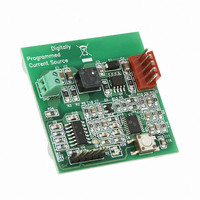
MCP1631RD-DCPC1
Description
REF DES BATT CHARG OR LED DRIVER
Manufacturer
Microchip Technology
Datasheets
1.PIC16F616T-ISL.pdf
(214 pages)
2.MCP1631VHVT-330EST.pdf
(34 pages)
3.MCP1631VHVT-330EST.pdf
(32 pages)
Specifications of MCP1631RD-DCPC1
Current - Output / Channel
700mA
Outputs And Type
1, Non-Isolated
Features
Firmware for Li-Ion, NiMH, and NiCd Battery Charger
Voltage - Input
3.5 ~ 16 V
Utilized Ic / Part
MCP1631HV, PIC16F616
Core Chip
MCP1631HV, PIC16F616
Topology
Parallel, Series
Output Current
1A
No. Of Outputs
1
Input Voltage
3.5V To 16V
Dimming Control Type
Analog
Kit Contents
Board
Lead Free Status / RoHS Status
Lead free / RoHS Compliant
Voltage - Output
-
Lead Free Status / Rohs Status
Lead free / RoHS Compliant


PIC16F610/616/16HV610/616
6.2.1
When the internal clock source is selected the
TMR1H:TMR1L register pair will increment on multiples
of T
6.2.2
When the external clock source is selected, the Timer1
module may work as a timer or a counter.
When counting, Timer1 is incremented on the rising
edge of the external clock input T1CKI. In addition, the
Counter mode clock can be synchronized to the
microcontroller system clock or run asynchronously.
If an external clock oscillator is needed (and the
microcontroller is using the INTOSC without CLKOUT),
Timer1 can use the LP oscillator as a clock source.
6.3
Timer1 has four prescaler options allowing 1, 2, 4 or 8
divisions of the clock input. The T1CKPS bits of the
T1CON register control the prescale counter. The
prescale counter is not directly readable or writable;
however, the prescaler counter is cleared upon a write to
TMR1H or TMR1L.
6.4
A low-power 32.768 kHz crystal oscillator is built-in
between pins OSC1 (input) and OSC2 (output). The
oscillator is enabled by setting the T1OSCEN control
bit of the T1CON register. The oscillator will continue to
run during Sleep.
The Timer1 oscillator is shared with the system LP
oscillator. Thus, Timer1 can use this mode only when
the primary system clock is derived from the internal
oscillator or when the oscillator is in the LP Oscillator
mode. The user must provide a software time delay to
ensure proper oscillator start-up.
TRISA5 and TRISA4 bits are set when the Timer1
oscillator is enabled. RA5 and RA4 bits read as ‘0’ and
TRISA5 and TRISA4 bits read as ‘1’.
DS41288F-page 50
Note:
Note:
CY
as determined by the Timer1 prescaler.
Timer1 Prescaler
Timer1 Oscillator
INTERNAL CLOCK SOURCE
EXTERNAL CLOCK SOURCE
In Counter mode, a falling edge must be
registered by the counter prior to the first
incrementing rising edge.
The oscillator requires a start-up and
stabilization time before use. Thus,
T1OSCEN should be set and a suitable
delay observed prior to enabling Timer1.
6.5
If control bit T1SYNC of the T1CON register is set, the
external clock input is not synchronized. The timer
continues to increment asynchronous to the internal
phase clocks. The timer will continue to run during
Sleep and can generate an interrupt on overflow,
which will wake-up the processor. However, special
precautions in software are needed to read/write the
timer (see Section 6.5.1 “Reading and Writing
Timer1 in Asynchronous Counter Mode”).
6.5.1
Reading TMR1H or TMR1L while the timer is running
from an external asynchronous clock will ensure a valid
read (taken care of in hardware). However, the user
should keep in mind that reading the 16-bit timer in two
8-bit values itself, poses certain problems, since the
timer may overflow between the reads.
For writes, it is recommended that the user simply stop
the timer and write the desired values. A write
contention may occur by writing to the timer registers,
while the register is incrementing. This may produce an
unpredictable value in the TMR1H:TMR1L register
pair.
6.6
Timer1 gate source is software configurable to be the
T1G pin or the output of Comparator C2. This allows the
device to directly time external events using T1G or
analog events using Comparator C2. See the
CM2CON1 register (Register 8-3) for selecting the
Timer1 gate source. This feature can simplify the
software for a Delta-Sigma A/D converter and many
Note:
Note:
Timer1 Operation in
Asynchronous Counter Mode
Timer1 Gate
When switching from synchronous to
asynchronous operation, it is possible to
skip an increment. When switching from
asynchronous to synchronous operation,
it is possible to produce an additional
increment.
In asynchronous counter mode or when
using the internal oscillator and T1ACS=1,
Timer1 can not be used as a time base for
the capture or compare modes of the
ECCP module (for PIC16F616/HV616
only).
READING AND WRITING TIMER1 IN
ASYNCHRONOUS COUNTER
MODE
© 2009 Microchip Technology Inc.
Related parts for MCP1631RD-DCPC1
Image
Part Number
Description
Manufacturer
Datasheet
Request
R

Part Number:
Description:
REFERENCE DESIGN MCP1631HV
Manufacturer:
Microchip Technology
Datasheet:

Part Number:
Description:
REFERENCE DESIGN FOR MCP1631HV
Manufacturer:
Microchip Technology
Datasheet:

Part Number:
Description:
Manufacturer:
Microchip Technology Inc.
Datasheet:
Part Number:
Description:
Manufacturer:
Microchip Technology Inc.
Datasheet:
Part Number:
Description:
Manufacturer:
Microchip Technology Inc.
Datasheet:
Part Number:
Description:
Manufacturer:
Microchip Technology Inc.
Datasheet:
Part Number:
Description:
Manufacturer:
Microchip Technology Inc.
Datasheet:
Part Number:
Description:
Manufacturer:
Microchip Technology Inc.
Datasheet:
Part Number:
Description:
Manufacturer:
Microchip Technology Inc.
Datasheet:
Part Number:
Description:
Manufacturer:
Microchip Technology Inc.
Datasheet: