MC56F8037EVM Freescale Semiconductor, MC56F8037EVM Datasheet - Page 146
MC56F8037EVM
Manufacturer Part Number
MC56F8037EVM
Description
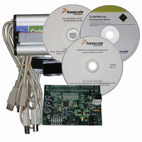
BOARD EVAL FOR MC56F8037
Manufacturer
Freescale Semiconductor
Type
MCUr
Datasheet
1.MC56F8037EVM.pdf
(180 pages)
Specifications of MC56F8037EVM
Contents
Board, Cables, CD, Debugger
Silicon Manufacturer
Freescale
Core Architecture
56800/E
Core Sub-architecture
56800/E
Silicon Core Number
MC56F
Silicon Family Name
MC56F80xx
Kit Contents
MC56F8037EVM, USB-JTAG Adapter, Cables, CD
Rohs Compliant
Yes
For Use With/related Products
MC56F8037
Lead Free Status / RoHS Status
Lead free / RoHS Compliant
Available stocks
Company
Part Number
Manufacturer
Quantity
Price
Company:

Part Number:
MC56F8037EVM
Manufacturer:
Freescale Semiconductor
Quantity:
135


1. No Output Switching
STANDBY > STOP
POWERDOWN
10.2.1
The 56F8037/56F8027 has two on-chip regulators. One supplies the PLL and relaxation oscillator. It has
no external pins and therefore has no external characteristics which must be guaranteed (other than proper
operation of the device). The second regulator supplies approximately 2.5V to the 56F8037/56F8027’s
core logic. This regulator requires an external 4.4
and tantalum capacitors tend to provide better performance tolerances. The output voltage can be
146
All ports configured as inputs
All inputs Low
No DC Loads
Mode
1. When V
2. When V
3. Power-On Reset occurs whenever the internally regulated 2.5V digital supply drops below 1.8V. While
Low-Voltage Interrupt for 3.3V supply
Low-Voltage Interrupt for 2.5V supply
Low-Voltage Interrupt Recovery Hysteresis
Power-On Reset
power is ramping up, this signal remains active for as long as the internal 2.5V is below 2.15V or the 3.3V
1/O voltage is below 2.7V, no matter how long the ramp-up rate is. The internally regulated voltage is
typically 100mV less than V
Voltage Regulator Specifications
Table 10-6 Current Consumption per Power Supply Pin (Continued)
DD
DD
100kHz Device Clock
Relaxation Oscillator in Standby mode
PLL powered off
Processor Core in STOP state
All peripheral module and core clocks are off
ADC/DAC/Comparator powered off
Voltage regulator in Standby mode
Device Clock is off
Relaxation Oscillator powered off
PLL powered off
Processor Core in STOP state
All peripheral module and core clocks are off
ADC /DAC/Comparator powered off
Voltage Regulator in Standby mode
drops below V
drops below V
Table 10-7 Power-On Reset Low-Voltage Parameters
Characteristic
3
EI3.3
EI32.5
DD
Conditions
, an interrupt is generated.
, an interrupt is generated.
during ramp-up until 2.5V is reached, at which time it self-regulates.
56F8037/56F8027 Data Sheet, Rev. 7
1
2
Symbol
V
F, or greater, capacitor for proper operation. Ceramic
V
POR
V
E12.5
EI3.3
EIH
2.58
Min
—
—
—
Typical @ 3.3V, 25°C
540A
440A
I
DD
1
2.15
Typ
2.7
1.8
50
I
0A
0A
DDA
Max
1.9
—
—
—
Freescale Semiconductor
Maximum@ 3.6V, 25°C
650A
550A
I
DD
Unit
mV
1
V
V
V
I
1A
1A
DDA
Related parts for MC56F8037EVM
Image
Part Number
Description
Manufacturer
Datasheet
Request
R

Part Number:
Description:
Manufacturer:
Freescale Semiconductor, Inc
Datasheet:
Part Number:
Description:
Manufacturer:
Freescale Semiconductor, Inc
Datasheet:
Part Number:
Description:
Manufacturer:
Freescale Semiconductor, Inc
Datasheet:
Part Number:
Description:
Manufacturer:
Freescale Semiconductor, Inc
Datasheet:
Part Number:
Description:
Manufacturer:
Freescale Semiconductor, Inc
Datasheet:
Part Number:
Description:
Manufacturer:
Freescale Semiconductor, Inc
Datasheet:
Part Number:
Description:
Manufacturer:
Freescale Semiconductor, Inc
Datasheet:
Part Number:
Description:
Manufacturer:
Freescale Semiconductor, Inc
Datasheet:
Part Number:
Description:
Manufacturer:
Freescale Semiconductor, Inc
Datasheet:
Part Number:
Description:
Manufacturer:
Freescale Semiconductor, Inc
Datasheet:
Part Number:
Description:
Manufacturer:
Freescale Semiconductor, Inc
Datasheet:
Part Number:
Description:
Manufacturer:
Freescale Semiconductor, Inc
Datasheet:
Part Number:
Description:
Manufacturer:
Freescale Semiconductor, Inc
Datasheet:
Part Number:
Description:
Manufacturer:
Freescale Semiconductor, Inc
Datasheet:
Part Number:
Description:
Manufacturer:
Freescale Semiconductor, Inc
Datasheet: