MC56F8037EVM Freescale Semiconductor, MC56F8037EVM Datasheet - Page 170
MC56F8037EVM
Manufacturer Part Number
MC56F8037EVM
Description
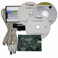
BOARD EVAL FOR MC56F8037
Manufacturer
Freescale Semiconductor
Type
MCUr
Datasheet
1.MC56F8037EVM.pdf
(180 pages)
Specifications of MC56F8037EVM
Contents
Board, Cables, CD, Debugger
Silicon Manufacturer
Freescale
Core Architecture
56800/E
Core Sub-architecture
56800/E
Silicon Core Number
MC56F
Silicon Family Name
MC56F80xx
Kit Contents
MC56F8037EVM, USB-JTAG Adapter, Cables, CD
Rohs Compliant
Yes
For Use With/related Products
MC56F8037
Lead Free Status / RoHS Status
Lead free / RoHS Compliant
Available stocks
Company
Part Number
Manufacturer
Quantity
Price
Company:

Part Number:
MC56F8037EVM
Manufacturer:
Freescale Semiconductor
Quantity:
135


Part 12 Design Considerations
12.1 Thermal Design Considerations
An estimation of the chip junction temperature, T
T
where:
The junction-to-ambient thermal resistance is an industry-standard value that provides a quick and easy
estimation of thermal performance. Unfortunately, there are two values in common usage: the value
determined on a single-layer board and the value obtained on a board with two planes. For packages such
as the PBGA, these values can be different by a factor of two. Which value is closer to the application
depends on the power dissipated by other components on the board. The value obtained on a single layer
board is appropriate for the tightly packed printed circuit board. The value obtained on the board with the
internal planes is usually appropriate if the board has low-power dissipation and the components are well
separated.
When a heat sink is used, the thermal resistance is expressed as the sum of a junction-to-case thermal
resistance and a case-to-ambient thermal resistance:
R
where:
R
change the case to ambient thermal resistance, R
sink, the air flow around the device, the interface material, the mounting arrangement on printed circuit
board, or change the thermal dissipation on the printed circuit board surrounding the device.
To determine the junction temperature of the device in the application when heat sinks are not used, the
Thermal Characterization Parameter (
measurement of the temperature at the top center of the package case using the following equation:
T
where:
170
T
R
P
R
R
R
T
P
J
J
D
JA
JC
D
A
T
J
JA
JC
CA
JT
= T
= T
is device related and cannot be influenced by the user. The user controls the thermal environment to
= R
A
T
= Ambient temperature for the package (
= Junction-to-ambient thermal resistance (
= Power dissipation in the package (W)
=
=
=
= Thermocouple temperature on top of package (
= Thermal characterization parameter (
= Power dissipation in package (W)
+ (
+ (R
JC
Package junction-to-ambient thermal resistance (°C/W)
Package junction-to-case thermal resistance (°C/W)
Package case-to-ambient thermal resistance (°C/W)
+ R
J
JT
x P
CA
x P
D
D
)
)
56F8037/56F8027 Data Sheet, Rev. 7
JT
) can be used to determine the junction temperature with a
CA
o
o
J
C/W)
, can be obtained from the equation:
C)
o
. For instance, the user can change the size of the heat
C/W)
o
C)
Freescale Semiconductor
Related parts for MC56F8037EVM
Image
Part Number
Description
Manufacturer
Datasheet
Request
R

Part Number:
Description:
Manufacturer:
Freescale Semiconductor, Inc
Datasheet:
Part Number:
Description:
Manufacturer:
Freescale Semiconductor, Inc
Datasheet:
Part Number:
Description:
Manufacturer:
Freescale Semiconductor, Inc
Datasheet:
Part Number:
Description:
Manufacturer:
Freescale Semiconductor, Inc
Datasheet:
Part Number:
Description:
Manufacturer:
Freescale Semiconductor, Inc
Datasheet:
Part Number:
Description:
Manufacturer:
Freescale Semiconductor, Inc
Datasheet:
Part Number:
Description:
Manufacturer:
Freescale Semiconductor, Inc
Datasheet:
Part Number:
Description:
Manufacturer:
Freescale Semiconductor, Inc
Datasheet:
Part Number:
Description:
Manufacturer:
Freescale Semiconductor, Inc
Datasheet:
Part Number:
Description:
Manufacturer:
Freescale Semiconductor, Inc
Datasheet:
Part Number:
Description:
Manufacturer:
Freescale Semiconductor, Inc
Datasheet:
Part Number:
Description:
Manufacturer:
Freescale Semiconductor, Inc
Datasheet:
Part Number:
Description:
Manufacturer:
Freescale Semiconductor, Inc
Datasheet:
Part Number:
Description:
Manufacturer:
Freescale Semiconductor, Inc
Datasheet:
Part Number:
Description:
Manufacturer:
Freescale Semiconductor, Inc
Datasheet: