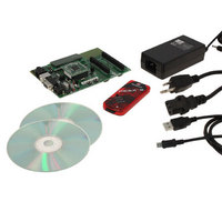
DV164136 Microchip Technology, DV164136 Datasheet - Page 431

DV164136
Manufacturer Part Number
DV164136
Description
DEVELOPMENT KIT FOR PIC18
Manufacturer
Microchip Technology
Series
PIC®r
Type
MCUr
Datasheets
1.DM183032.pdf
(38 pages)
2.DV164136.pdf
(448 pages)
3.DV164136.pdf
(6 pages)
4.DV164136.pdf
(446 pages)
5.DV164136.pdf
(4 pages)
6.DV164136.pdf
(18 pages)
Specifications of DV164136
Contents
Board, Cables, CDs, PICkit™ 3 Programmer, Power Supply
Processor To Be Evaluated
PIC18F8722, PIC18F87J11
Interface Type
RS-232, USB
Operating Supply Voltage
3.3 V, 5 V
Silicon Manufacturer
Microchip
Core Architecture
PIC
Core Sub-architecture
PIC18
Silicon Core Number
PIC18F
Silicon Family Name
PIC18F8xxx
Kit Contents
PIC18 Exp Brd PICkit 3 Cable CD PSU
Lead Free Status / RoHS Status
Lead free / RoHS Compliant
For Use With/related Products
PIC18F8722, PIC18F87J11
Lead Free Status / Rohs Status
Lead free / RoHS Compliant
Available stocks
Company
Part Number
Manufacturer
Quantity
Price
Company:
Part Number:
DV164136
Manufacturer:
MICROCHIP
Quantity:
12 000
- DM183032 PDF datasheet
- DV164136 PDF datasheet #2
- DV164136 PDF datasheet #3
- DV164136 PDF datasheet #4
- DV164136 PDF datasheet #5
- DV164136 PDF datasheet #6
- Current page: 431 of 446
- Download datasheet (7Mb)
INDEX
A
A/D ................................................................................... 271
Absolute Maximum Ratings ............................................. 375
AC (Timing) Characteristics ............................................. 396
Access Bank
ACKSTAT ........................................................................ 236
ACKSTAT Status Flag ..................................................... 236
ADCON0 Register ............................................................ 271
ADCON1 Register ............................................................ 271
ADCON2 Register ............................................................ 271
ADDFSR .......................................................................... 364
ADDLW ............................................................................ 327
ADDULNK ........................................................................ 364
ADDWF ............................................................................ 327
ADDWFC ......................................................................... 328
ADRESH Register ............................................................ 271
ADRESL Register .................................................... 271, 274
Analog-to-Digital Converter. See A/D.
ANDLW ............................................................................ 328
ANDWF ............................................................................ 329
Assembler
Auto-Wake-up on Sync Break Character ......................... 262
B
Bank Select Register (BSR) ............................................... 72
Baud Rate Generator ....................................................... 232
BC .................................................................................... 329
BCF .................................................................................. 330
BF .................................................................................... 236
BF Status Flag ................................................................. 236
Block Diagrams
© 2008 Microchip Technology Inc.
A/D Converter Interrupt, Configuring ....................... 275
Acquisition Requirements ........................................ 276
ADCON0 Register .................................................... 271
ADCON1 Register .................................................... 271
ADCON2 Register .................................................... 271
ADRESH Register ............................................ 271, 274
ADRESL Register .................................................... 271
Analog Port Pins ...................................................... 158
Analog Port Pins, Configuring .................................. 278
Associated Registers ............................................... 280
Configuring the Module ............................................ 275
Conversion Clock (T
Conversion Status (GO/DONE Bit) .......................... 274
Conversions ............................................................. 279
Converter Characteristics ........................................ 416
Discharge ................................................................. 279
Operation in Power-Managed Modes ...................... 278
Selecting and Configuring Acquisition Time ............ 277
Special Event Trigger (ECCP) ................................. 192
Special Event Trigger (ECCP2) ............................... 280
Use of the ECCP2 Trigger ....................................... 280
Load Conditions for Device
Parameter Symbology ............................................. 396
Temperature and Voltage Specifications ................. 397
Timing Conditions .................................................... 397
Mapping in Indexed Literal Offset Mode .................... 85
GO/DONE Bit ........................................................... 274
MPASM Assembler .................................................. 372
16-Bit Byte Select Mode .......................................... 103
16-Bit Byte Write Mode ............................................ 101
16-Bit Word Write Mode ........................................... 102
A/D ........................................................................... 274
Timing Specifications ....................................... 397
AD
) ........................................... 277
BN .................................................................................... 330
BNC ................................................................................. 331
BNN ................................................................................. 331
BNOV .............................................................................. 332
BNZ ................................................................................. 332
BOR. See Brown-out Reset.
BOV ................................................................................. 335
BRA ................................................................................. 333
Break Character (12-Bit) Transmit and Receive .............. 263
BRG. See Baud Rate Generator.
Brown-out Reset (BOR) ..................................................... 52
BSF .................................................................................. 333
BTFSC ............................................................................. 334
BTFSS ............................................................................. 334
BTG ................................................................................. 335
BZ .................................................................................... 336
PIC18F8722 FAMILY
Analog Input Model .................................................. 275
Baud Rate Generator .............................................. 232
Capture Mode Operation ......................................... 181
Comparator Analog Input Model .............................. 285
Comparator I/O Operating Modes ........................... 282
Comparator Output .................................................. 284
Comparator Voltage Reference ............................... 288
Comparator Voltage Reference Output
Compare Mode Operation ....................................... 182
Device Clock .............................................................. 37
Enhanced PWM ....................................................... 193
EUSART Receive .................................................... 260
EUSART Transmit ................................................... 258
External Power-on Reset Circuit
Fail-Safe Clock Monitor (FSCM) .............................. 315
Generic I/O Port Operation ...................................... 135
High/Low-Voltage Detect with External Input .......... 292
HSPLL ....................................................................... 33
Interrupt Logic .......................................................... 120
INTOSC and PLL ....................................................... 34
MSSP (I
MSSP (I
MSSP (SPI Mode) ................................................... 205
On-Chip Reset Circuit ................................................ 49
PIC18F6527/6622/6627/6722 ................................... 11
PIC18F8527/8622/8627/8722 ................................... 12
PORTD and PORTE (Parallel Slave Port) ............... 158
PWM Operation (Simplified) .................................... 184
Reads from Flash Program Memory ......................... 91
Single Comparator ................................................... 283
Table Read Operation ............................................... 87
Table Write Operation ............................................... 88
Table Writes to Flash Program Memory .................... 93
Timer0 in 16-Bit Mode ............................................. 162
Timer0 in 8-Bit Mode ............................................... 162
Timer1 ..................................................................... 166
Timer1 (16-Bit Read/Write Mode) ............................ 166
Timer2 ..................................................................... 172
Timer3 ..................................................................... 174
Timer3 (16-Bit Read/Write Mode) ............................ 174
Timer4 ..................................................................... 178
Watchdog Timer ...................................................... 312
Detecting ................................................................... 52
Disabling in Sleep Mode ............................................ 52
Software Enabled ...................................................... 52
Buffer Example ................................................ 289
(Slow V
2
2
C Master Mode) ........................................ 230
C Mode) .................................................... 215
DD
Power-up) ........................................ 51
DS39646C-page 429
Related parts for DV164136
Image
Part Number
Description
Manufacturer
Datasheet
Request
R

Part Number:
Description:
Manufacturer:
Microchip Technology Inc.
Datasheet:

Part Number:
Description:
Manufacturer:
Microchip Technology Inc.
Datasheet:

Part Number:
Description:
Manufacturer:
Microchip Technology Inc.
Datasheet:

Part Number:
Description:
Manufacturer:
Microchip Technology Inc.
Datasheet:

Part Number:
Description:
Manufacturer:
Microchip Technology Inc.
Datasheet:

Part Number:
Description:
Manufacturer:
Microchip Technology Inc.
Datasheet:

Part Number:
Description:
Manufacturer:
Microchip Technology Inc.
Datasheet:

Part Number:
Description:
Manufacturer:
Microchip Technology Inc.
Datasheet:


