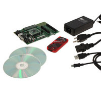
DV164136 Microchip Technology, DV164136 Datasheet - Page 438

DV164136
Manufacturer Part Number
DV164136
Description
DEVELOPMENT KIT FOR PIC18
Manufacturer
Microchip Technology
Series
PIC®r
Type
MCUr
Datasheets
1.DM183032.pdf
(38 pages)
2.DV164136.pdf
(448 pages)
3.DV164136.pdf
(6 pages)
4.DV164136.pdf
(446 pages)
5.DV164136.pdf
(4 pages)
6.DV164136.pdf
(18 pages)
Specifications of DV164136
Contents
Board, Cables, CDs, PICkit™ 3 Programmer, Power Supply
Processor To Be Evaluated
PIC18F8722, PIC18F87J11
Interface Type
RS-232, USB
Operating Supply Voltage
3.3 V, 5 V
Silicon Manufacturer
Microchip
Core Architecture
PIC
Core Sub-architecture
PIC18
Silicon Core Number
PIC18F
Silicon Family Name
PIC18F8xxx
Kit Contents
PIC18 Exp Brd PICkit 3 Cable CD PSU
Lead Free Status / RoHS Status
Lead free / RoHS Compliant
For Use With/related Products
PIC18F8722, PIC18F87J11
Lead Free Status / Rohs Status
Lead free / RoHS Compliant
Available stocks
Company
Part Number
Manufacturer
Quantity
Price
Company:
Part Number:
DV164136
Manufacturer:
MICROCHIP
Quantity:
12 000
- DM183032 PDF datasheet
- DV164136 PDF datasheet #2
- DV164136 PDF datasheet #3
- DV164136 PDF datasheet #4
- DV164136 PDF datasheet #5
- DV164136 PDF datasheet #6
- Current page: 438 of 446
- Download datasheet (7Mb)
PIC18F8722 FAMILY
PWM (CCP Module)
PWM (ECCP Module) ...................................................... 192
Q
Q Clock .................................................................... 185, 193
R
RAM. See Data Memory.
RC Oscillator ...................................................................... 33
RC_IDLE Mode .................................................................. 47
RC_RUN Mode .................................................................. 43
RCALL .............................................................................. 351
RCON Register
Reader Response ............................................................ 440
Register File ....................................................................... 74
Registers
DS39646C-page 436
Associated Registers ............................................... 186
Duty Cycle ................................................................ 184
Example Frequencies/Resolutions .......................... 185
Period ....................................................................... 184
Setup for PWM Operation ........................................ 185
TMR2 to PR2 Match ................................................ 184
TMR4 to PR4 Match ................................................ 177
Associated Registers ............................................... 204
CCPR1H:CCPR1L Registers ................................... 192
Direction Change in Full-Bridge Output Mode ......... 198
Duty Cycle ................................................................ 193
Effects of a Reset ..................................................... 203
Enhanced PWM Auto-Shutdown ............................. 200
Example Frequencies/Resolutions .......................... 193
Full-Bridge Application Example .............................. 198
Full-Bridge Mode ...................................................... 197
Half-Bridge Mode ..................................................... 196
Half-Bridge Output Mode
Operation in Power-Managed Modes ...................... 203
Operation with Fail-Safe Clock Monitor ................... 203
Output Configurations .............................................. 194
Output Relationships (Active-High) .......................... 194
Output Relationships (Active-Low) ........................... 195
Period ....................................................................... 192
Programmable Dead-Band Delay ............................ 200
Setup for PWM Operation ........................................ 203
Start-up Considerations ........................................... 202
TMR2 to PR2 Match ................................................ 192
RCIO Oscillator Mode ................................................ 33
Bit Status During Initialization .................................... 56
ADCON0 (A/D Control 0) ......................................... 271
ADCON1 (A/D Control 1) ......................................... 272
ADCON2 (A/D Control 2) ......................................... 273
BAUDCONx (Baud Rate Control) ............................ 250
CCPxCON (CCPx Control, CCP4 and CCP5) ......... 179
CMCON (Comparator Control) ................................ 281
CONFIG1H (Configuration 1 High) .......................... 299
CONFIG2H (Configuration 2 High) .......................... 301
CONFIG2L (Configuration 2 Low) ............................ 300
CONFIG3H (Configuration 3 High) .......................... 303
CONFIG3L (Configuration 3 Low) ............................ 302
CONFIG4L (Configuration 4 Low) ............................ 304
CONFIG5H (Configuration 5 High) .......................... 306
CONFIG5L (Configuration 5 Low) ............................ 305
CONFIG6H (Configuration 6 High) .......................... 308
CONFIG6L (Configuration 6 Low) ............................ 307
CONFIG7H (Configuration 7 High) .......................... 310
CONFIG7L (Configuration 7 Low) ............................ 309
DEVID1 (Device ID 1) .............................................. 311
Applications Example ....................................... 196
RESET ............................................................................. 351
Reset State of Registers .................................................... 56
Resets ........................................................................ 49, 297
RETFIE ............................................................................ 352
RETLW ............................................................................ 352
RETURN .......................................................................... 353
Return Address Stack ........................................................ 66
Return Stack Pointer (STKPTR) ........................................ 67
Revision History ............................................................... 425
RLCF ............................................................................... 353
RLNCF ............................................................................. 354
RRCF ............................................................................... 354
RRNCF ............................................................................ 355
S
SCKx ................................................................................ 205
SDIx ................................................................................. 205
SDOx ............................................................................... 205
SEC_IDLE Mode ............................................................... 46
SEC_RUN Mode ................................................................ 42
Serial Clock, SCKx .......................................................... 205
Serial Data In (SDIx) ........................................................ 205
Serial Data Out (SDOx) ................................................... 205
Serial Peripheral Interface. See SPI Mode.
SETF ................................................................................ 355
Single-Supply ICSP Programming.
Slave Select (SSx) ........................................................... 205
Slave Select Synchronization .......................................... 211
SLEEP ............................................................................. 356
DEVID2 (Device ID 2) .............................................. 311
ECCPxDEL (Enhanced PWM
EECON1 (Data EEPROM Control 1) ....................... 112
EECON1 (EEPROM Control 1) ................................. 89
HLVDCON (High/Low-Voltage Detect Control) ....... 291
INTCON (Interrupt Control) ...................................... 121
INTCON2 (Interrupt Control 2) ................................. 122
INTCON3 (Interrupt Control 3) ................................. 123
IPR1 (Peripheral Interrupt Priority 1) ....................... 130
IPR2 (Peripheral Interrupt Priority 2) ....................... 131
MEMCON (External Memory Bus Control) ................ 98
OSCCON (Oscillator Control) .................................... 39
OSCTUNE (Oscillator Tuning) ................................... 35
PIR1 (Peripheral Interrupt Request (Flag) 1) ........... 124
PIR2 (Peripheral Interrupt Request (Flag) 2) ........... 125
PSPCON (Parallel Slave Port Control) .................... 159
RCON (Reset Control) ....................................... 50, 133
RCSTAx (Receive Status and Control) .................... 249
SSPxCON1 (MSSPx Control 1, I
SSPxCON1 (MSSPx Control 1, SPI Mode) ............. 207
SSPxCON2 (MSSPx Control 2, I
SSPxSTAT (MSSPx Status, I
SSPxSTAT (MSSPx Status, SPI Mode) .................. 206
STATUS (Arithmetic Status) ...................................... 80
STKPTR (Stack Pointer) ............................................ 67
T0CON (Timer0 Control) ......................................... 161
T1CON (Timer1 Control) ......................................... 165
T2CON (Timer2 Control) ......................................... 171
T3CON (Timer3 Control) ......................................... 173
T4CON (Timer 4 Control) ........................................ 177
TXSTAx (Transmit Status and Control) ................... 248
WDTCON (Watchdog Timer Control) ...................... 313
Brown-out Reset (BOR) ........................................... 297
Oscillator Start-up Timer (OST) ............................... 297
Power-on Reset (POR) ............................................ 297
Power-up Timer (PWRT) ......................................... 297
Dead-Band Delay) ........................................... 200
© 2008 Microchip Technology Inc.
2
C Mode) ................... 216
2
2
C Mode) .............. 217
C Mode) .............. 219
Related parts for DV164136
Image
Part Number
Description
Manufacturer
Datasheet
Request
R

Part Number:
Description:
Manufacturer:
Microchip Technology Inc.
Datasheet:

Part Number:
Description:
Manufacturer:
Microchip Technology Inc.
Datasheet:

Part Number:
Description:
Manufacturer:
Microchip Technology Inc.
Datasheet:

Part Number:
Description:
Manufacturer:
Microchip Technology Inc.
Datasheet:

Part Number:
Description:
Manufacturer:
Microchip Technology Inc.
Datasheet:

Part Number:
Description:
Manufacturer:
Microchip Technology Inc.
Datasheet:

Part Number:
Description:
Manufacturer:
Microchip Technology Inc.
Datasheet:

Part Number:
Description:
Manufacturer:
Microchip Technology Inc.
Datasheet:


