EVAL-ADUC832QSZ Analog Devices Inc, EVAL-ADUC832QSZ Datasheet - Page 35
EVAL-ADUC832QSZ
Manufacturer Part Number
EVAL-ADUC832QSZ
Description
KIT DEV FOR ADUC832 QUICK START
Manufacturer
Analog Devices Inc
Series
QuickStart™ Kitr
Type
MCUr
Specifications of EVAL-ADUC832QSZ
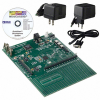
Contents
Evaluation Board, Cable, Power Supply, Software and Documentation
Lead Free Status / RoHS Status
Lead free / RoHS Compliant
For Use With/related Products
ADuC832
Lead Free Status / RoHS Status
Compliant, Lead free / RoHS Compliant
Other names
EVAL-ADUC832QS
EVAL-ADUC832QS
EVAL-ADUC832QS


ON-CHIP PLL
The ADuC832 is intended for use with a 32.768 kHz watch
crystal. A PLL locks onto a multiple (512) of this to provide a
stable 16.78 MHz clock for the system. The core can operate at
this frequency or at binary submultiples of it to allow power
saving in cases where maximum core performance is not
required. The default core clock is the PLL clock divided by
8 or 2.097152 MHz. The ADC clocks are also derived from the
Bit
7
6
5
4
3
2
1
0
REV. 0
Name
OSC_PD
LOCK
----
----
FINT
CD2
CD1
CD0
Description
Oscillator Power-Down Bit.
Set by user to halt the 32 kHz oscillator in power-down mode.
Cleared by user to enable the 32 kHz oscillator in power-down mode.
This feature allows the TIC to continue counting even in power-down mode.
PLL Lock Bit.
This is a read only bit.
Set automatically at power-on to indicate the PLL loop is correctly tracking the crystal clock.
If the external crystal becomes subsequently disconnected, the PLL will rail and the core will halt.
Cleared automatically at power-on to indicate the PLL is not correctly tracking the crystal clock. This
may be due to the absence of a crystal clock or an external crystal at power-on. In this mode, the PLL
output can be 16.78 MHz ± 20%.
Reserved for future use; should be written with “0.”
Reserved for future use; should be written with “0.”
Fast Interrupt Response Bit
Set by user enabling the response to any interrupt to be executed at the fastest core clock frequency,
regardless of the configuration of the CD2–0 bits (see below). Once user code has returned from an
interrupt, the core resumes code execution at the core clock selected by the CD2–0 bits.
Cleared by user to disable the fast interrupt response feature.
CPU (Core Clock) Divider Bits.
This number determines the frequency at which the microcontroller core will operate.
CD2
0
0
0
0
1
1
1
1
CD1
0
0
1
1
0
0
1
1
Table X. PLLCON SFR Bit Designations
CD0
0
1
0
1
0
1
0
1
–35–
PLL clock, with the modulator rate being the same as the crys-
tal oscillator frequency. The above choice of frequencies ensures
that the modulators and the core will be synchronous, regardless
of the core clock rate. The PLL control register is PLLCON.
PLLCON
SFR Address
Power-On Default Value
Bit Addressable
Core Clock Frequency (MHz)
16.777216
8.388608
4.194304
2.097152
1.048576
0.524288
0.262144
0.131072
(Default Core Clock
Frequency)
PLL Control Register
D7H
53H
No
ADuC832
Related parts for EVAL-ADUC832QSZ
Image
Part Number
Description
Manufacturer
Datasheet
Request
R


Part Number:
Description:
BOARD EVAL FOR SI270X-A
Manufacturer:
Silicon Laboratories Inc
Datasheet:

Part Number:
Description:
BUCK CONV REF DESIGN KIT IP1201
Manufacturer:
International Rectifier
Datasheet:
Part Number:
Description:
BOARD DEMO SYNC DUAL BUCK CNVTER
Manufacturer:
International Rectifier
Datasheet:
Part Number:
Description:
BOARD DEMO SYNC BUCK CONVETER
Manufacturer:
International Rectifier
Datasheet:

Part Number:
Description:
EVALBOARD/EB Omnidirectional microphone - Analog
Manufacturer:
Analog Devices
Datasheet:
Part Number:
Description:
EVALBOARD/EB Omnidirectional microphone - Analog
Manufacturer:
Analog Devices
Datasheet:


Part Number:
Description:
BOARD EVAL LED DRIVER LT3756
Manufacturer:
Linear Technology
Datasheet:

Part Number:
Description:
BOARD EVAL FOR AD7741/7742
Manufacturer:
Analog Devices Inc
Datasheet:

Part Number:
Description:
±1.7g Dual-Axis IMEMS Accelerometer Evaluation Board
Manufacturer:
Analog Devices Inc
Datasheet:

Part Number:
Description:
IC MULTIPLIER ANALOG 8-SOIC T/R
Manufacturer:
Analog Devices Inc
Datasheet:

Part Number:
Description:
IC ANALOG MULTIPLIER 8-DIP
Manufacturer:
Analog Devices Inc
Datasheet:
Part Number:
Description:
IC ANALOG MULTIPLIER 8-SOIC
Manufacturer:
Analog Devices Inc
Datasheet:
Part Number:
Description:
IC ANALOG MULTIPLIER 8-DIP
Manufacturer:
Analog Devices Inc
Datasheet: