EVAL-ADUC832QSZ Analog Devices Inc, EVAL-ADUC832QSZ Datasheet - Page 37
EVAL-ADUC832QSZ
Manufacturer Part Number
EVAL-ADUC832QSZ
Description
KIT DEV FOR ADUC832 QUICK START
Manufacturer
Analog Devices Inc
Series
QuickStart™ Kitr
Type
MCUr
Specifications of EVAL-ADUC832QSZ
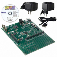
Contents
Evaluation Board, Cable, Power Supply, Software and Documentation
Lead Free Status / RoHS Status
Lead free / RoHS Compliant
For Use With/related Products
ADuC832
Lead Free Status / RoHS Status
Compliant, Lead free / RoHS Compliant
Other names
EVAL-ADUC832QS
EVAL-ADUC832QS
EVAL-ADUC832QS


PWM MODES OF OPERATION
MODE 0: PWM Disabled
The PWM is disabled allowing P2.6 and P2.7 to be used
as normal.
MODE 1: Single Variable Resolution PWM
In Mode 1, both the pulse length and the cycle time (period) are
programmable in user code, allowing the resolution of the PWM
to be variable.
PWM1H/L sets the period of the output waveform. Reducing
PWM1H/L reduces the resolution of the PWM output but
increases the maximum output rate of the PWM. (e.g., setting
PWM1H/L to 65536 gives a 16-bit PWM with a maximum
output rate of 266 Hz (16.777MHz/65536). Setting PWM1H/L
to 4096 gives a 12-bit PWM with a maximum output rate of
4096 Hz (16.777MHz/4096)).
PWM0H/L sets the duty cycle of the PWM output waveform, as
shown in Figure 27.
MODE 2: Twin 8-Bit PWM
In Mode 2, the duty cycle of the PWM outputs and the resolution
of the PWM outputs are both programmable. The maximum
resolution of the PWM output is eight bits.
PWM1L sets the period for both PWM outputs. Typically, this
will be set to 255 (FFH) to give an 8-bit PWM although it is pos-
sible to reduce this as necessary. A value of 100 could be loaded
here to give a percentage PWM (i.e., the PWM is accurate to 1%).
The outputs of the PWM at P2.6 and P2.7 are shown in Figure 28.
As can be seen, the output of PWM0 (P2.6) goes low when the
PWM counter equals PWM0L. The output of PWM1 (P2.7) goes
high when the PWM counter equals PWM1H and goes low
again when the PWM counter equals PWM0H. Setting PWM1H
to 0 ensures that both PWM outputs start simultaneously.
REV. 0
Figure 27. ADuC832 PWM in Mode 1
PWM COUNTER
PWM1H/L
PWM0H/L
P2.7
0
–37–
MODE 3: Twin 16-Bit PWM
In Mode 3, the PWM counter is fixed to count from 0 to 65536,
giving a fixed 16-bit PWM. Operating from the 16.777 MHz
core clock results in a PWM output rate of 256 Hz. The duty
cycle of the PWM outputs at P2.6 and P2.7 is independently
programmable.
As shown in Figure 29, while the PWM counter is less than
PWM0H/L, the output of PWM0 (P2.6) is high. Once the PWM
counter equals PWM0H/L, PWM0 (P2.6) goes low and remains
low until the PWM counter rolls over.
Similarly, while the PWM counter is less than PWM1H/L, the
output of PWM1 (P2.7) is high. Once the PWM counter equals
PWM1H/L, PWM1 (P2.7) goes low and remains low until the
PWM counter rolls over.
In this mode, both PWM outputs are synchronized, i.e., once the
PWM counter rolls over to 0, both PWM0 (P2.6) and PWM1
(P2.7) will go high.
Figure 28. PWM Mode 2
Figure 29. PWM Mode 3
PWM COUNTER
PWM COUNTER
ADuC832
65536
PWM1H/L
PWM0H/L
0
P2.6
P2.7
PWM1L
PWM0H
PWM0L
PWM1H
P2.6
P2.7
0
Related parts for EVAL-ADUC832QSZ
Image
Part Number
Description
Manufacturer
Datasheet
Request
R


Part Number:
Description:
BOARD EVAL FOR SI270X-A
Manufacturer:
Silicon Laboratories Inc
Datasheet:

Part Number:
Description:
BUCK CONV REF DESIGN KIT IP1201
Manufacturer:
International Rectifier
Datasheet:
Part Number:
Description:
BOARD DEMO SYNC DUAL BUCK CNVTER
Manufacturer:
International Rectifier
Datasheet:
Part Number:
Description:
BOARD DEMO SYNC BUCK CONVETER
Manufacturer:
International Rectifier
Datasheet:

Part Number:
Description:
EVALBOARD/EB Omnidirectional microphone - Analog
Manufacturer:
Analog Devices
Datasheet:
Part Number:
Description:
EVALBOARD/EB Omnidirectional microphone - Analog
Manufacturer:
Analog Devices
Datasheet:


Part Number:
Description:
BOARD EVAL LED DRIVER LT3756
Manufacturer:
Linear Technology
Datasheet:

Part Number:
Description:
BOARD EVAL FOR AD7741/7742
Manufacturer:
Analog Devices Inc
Datasheet:

Part Number:
Description:
±1.7g Dual-Axis IMEMS Accelerometer Evaluation Board
Manufacturer:
Analog Devices Inc
Datasheet:

Part Number:
Description:
IC MULTIPLIER ANALOG 8-SOIC T/R
Manufacturer:
Analog Devices Inc
Datasheet:

Part Number:
Description:
IC ANALOG MULTIPLIER 8-DIP
Manufacturer:
Analog Devices Inc
Datasheet:
Part Number:
Description:
IC ANALOG MULTIPLIER 8-SOIC
Manufacturer:
Analog Devices Inc
Datasheet:
Part Number:
Description:
IC ANALOG MULTIPLIER 8-DIP
Manufacturer:
Analog Devices Inc
Datasheet: