EVAL-ADUC832QSZ Analog Devices Inc, EVAL-ADUC832QSZ Datasheet - Page 44
EVAL-ADUC832QSZ
Manufacturer Part Number
EVAL-ADUC832QSZ
Description
KIT DEV FOR ADUC832 QUICK START
Manufacturer
Analog Devices Inc
Series
QuickStart™ Kitr
Type
MCUr
Specifications of EVAL-ADUC832QSZ
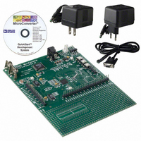
Contents
Evaluation Board, Cable, Power Supply, Software and Documentation
Lead Free Status / RoHS Status
Lead free / RoHS Compliant
For Use With/related Products
ADuC832
Lead Free Status / RoHS Status
Compliant, Lead free / RoHS Compliant
Other names
EVAL-ADUC832QS
EVAL-ADUC832QS
EVAL-ADUC832QS


ADuC832
PSMCON
SFR Address
Power-On Default Value
Bit Addressable
Bit
7
6
5
4
3
2
1
0
POWER SUPPLY MONITOR
As its name suggests, the Power Supply Monitor, once enabled,
monitors the DV
any of the supply pins drop below one of four user-selectable
voltage trip points from 2.63 V to 4.37 V. For correct operation
of the Power Supply Monitor function, AV
or greater than 2.7 V. Monitor function is controlled via the
PSMCON SFR. If enabled via the IEIP2 SFR, the monitor will
Name
----
CMPD
PSMI
TPD1
TPD0
----
----
PSMEN
DD
supply on the ADuC832. It will indicate when
Power Supply Monitor Control Register
DFH
DEH
No
Description
Reserved.
DV
This is a read-only bit and directly reflects the state of the DV
Read “1” indicates the DV
Read “0” indicates the DV
Power Supply Monitor Interrupt Bit.
This bit will be set high by the MicroConverter if either CMPA or CMPD is low, indicating low analog
or digital supply. The PSMI bit can be used to interrupt the processor. Once CMPD and/or CMPA
return (and remain) high, a 250 ms counter is started. When this counter times out, the PSMI interrupt is
cleared. PSMI can also be written by the user. However, if either comparator output is low, it is not
possible for the user to clear PSMI.
DV
These bits select the DV
TPD1
0
0
1
1
Reserved
Reserved
Power Supply Monitor Enable Bit.
Set to “1” by the user to enable the Power Supply Monitor Circuit.
Cleared to “0” by the user to disable the Power Supply Monitor Circuit.
DD
DD
Comparator Bit.
Trip Point Selection Bits.
DD
Table XV. PSMCON SFR Bit Designations
TPD0
0
1
0
1
must be equal to
DD
DD
DD
trip point voltage as follows:
supply is above its selected trip point.
supply is below its selected trip point.
Selected DV
4.37
3.08
2.93
2.63
–44–
interrupt the core using the PSMI bit in the PSMCON SFR.
This bit will not be cleared until the failing power supply has
returned above the trip point for at least 250 ms. This monitor
function allows the user to save working registers to avoid pos-
sible data loss due to the low supply condition, and also ensures
that normal code execution will not resume until a safe supply
level has been well established. The supply monitor is also pro-
tected against spurious glitches triggering the interrupt circuit.
DD
Trip Point (V)
DD
comparator.
REV. 0
Related parts for EVAL-ADUC832QSZ
Image
Part Number
Description
Manufacturer
Datasheet
Request
R


Part Number:
Description:
BOARD EVAL FOR SI270X-A
Manufacturer:
Silicon Laboratories Inc
Datasheet:

Part Number:
Description:
BUCK CONV REF DESIGN KIT IP1201
Manufacturer:
International Rectifier
Datasheet:
Part Number:
Description:
BOARD DEMO SYNC DUAL BUCK CNVTER
Manufacturer:
International Rectifier
Datasheet:
Part Number:
Description:
BOARD DEMO SYNC BUCK CONVETER
Manufacturer:
International Rectifier
Datasheet:

Part Number:
Description:
EVALBOARD/EB Omnidirectional microphone - Analog
Manufacturer:
Analog Devices
Datasheet:
Part Number:
Description:
EVALBOARD/EB Omnidirectional microphone - Analog
Manufacturer:
Analog Devices
Datasheet:


Part Number:
Description:
BOARD EVAL LED DRIVER LT3756
Manufacturer:
Linear Technology
Datasheet:

Part Number:
Description:
BOARD EVAL FOR AD7741/7742
Manufacturer:
Analog Devices Inc
Datasheet:

Part Number:
Description:
±1.7g Dual-Axis IMEMS Accelerometer Evaluation Board
Manufacturer:
Analog Devices Inc
Datasheet:

Part Number:
Description:
IC MULTIPLIER ANALOG 8-SOIC T/R
Manufacturer:
Analog Devices Inc
Datasheet:

Part Number:
Description:
IC ANALOG MULTIPLIER 8-DIP
Manufacturer:
Analog Devices Inc
Datasheet:
Part Number:
Description:
IC ANALOG MULTIPLIER 8-SOIC
Manufacturer:
Analog Devices Inc
Datasheet:
Part Number:
Description:
IC ANALOG MULTIPLIER 8-DIP
Manufacturer:
Analog Devices Inc
Datasheet: