EVAL-ADUC832QSZ Analog Devices Inc, EVAL-ADUC832QSZ Datasheet - Page 57
EVAL-ADUC832QSZ
Manufacturer Part Number
EVAL-ADUC832QSZ
Description
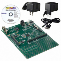
KIT DEV FOR ADUC832 QUICK START
Manufacturer
Analog Devices Inc
Series
QuickStart™ Kitr
Type
MCUr
Specifications of EVAL-ADUC832QSZ
Contents
Evaluation Board, Cable, Power Supply, Software and Documentation
Lead Free Status / RoHS Status
Lead free / RoHS Compliant
For Use With/related Products
ADuC832
Lead Free Status / RoHS Status
Compliant, Lead free / RoHS Compliant
Other names
EVAL-ADUC832QS
EVAL-ADUC832QS
EVAL-ADUC832QS


Mode 0: 8-Bit Shift Register Mode
Mode 0 is selected by clearing both the SM0 and SM1 bits in the
SFR SCON. Serial data enters and exits through RxD. TxD
outputs the shift clock. Eight data bits are transmitted or received.
Transmission is initiated by any instruction that writes to SBUF.
The data is shifted out of the RxD line. The eight bits are
transmitted with the least-significant bit (LSB) first, as shown
in Figure 51.
Reception is initiated when the receive enable bit (REN) is 1 and
the receive interrupt bit (RI) is 0. When RI is cleared the data is
clocked into the RxD line and the clock pulses are output from
the TxD line.
Mode 1: 8-Bit UART, Variable Baud Rate
Mode 1 is selected by clearing SM0 and setting SM1. Each data
byte (LSB first) is preceded by a start bit (0) and followed by a stop
bit (1). Therefore, 10 bits are transmitted on TxD or received on
RxD. The baud rate is set by the Timer 1 or Timer 2 overflow
rate, or a combination of the two (one for transmission and the
other for reception).
Transmission is initiated by writing to SBUF. The “write to SBUF”
signal also loads a 1 (stop bit) into the ninth bit position of the
transmit shift register. The data is output bit by bit until the
stop bit appears on TxD and the transmit interrupt flag (TI) is
automatically set as shown in Figure 52.
Reception is initiated when a 1-to-0 transition is detected on
RxD. Assuming a valid start bit was detected, character reception
continues. The start bit is skipped and the eight data bits are
clocked into the serial port shift register. When all eight bits have
been clocked in, the following events occur:
This will be the case if, and only if, the following conditions are
met at the time the final shift pulse is generated:
If either of these conditions is not met, the received frame is
irretrievably lost, and RI is not set.
REV. 0
(SHIFT CLOCK)
The eight bits in the receive shift register are latched into SBUF.
The ninth bit (Stop bit) is clocked into RB8 in SCON.
The Receiver Interrupt flag (RI) is set.
stop bit = 1.
RI = 0, and either SM2 = 0 or SM2 = 1, and the received
(DATA OUT)
(SCON.1)
Figure 51. UART Serial Port Transmission, Mode 0
Figure 52. UART Serial Port Transmission, Mode 0
CORE
TxD
CLK
ALE
RxD
TxD
TI
START
BIT
S1
S2
D0
MACHINE
DATA BIT 0
CYCLE 1
S3
S4
D1
S5
D2
S6
S1
DATA BIT 1
D3
S2
MACHINE
CYCLE 2
S3
D4
S4
D5
MACHINE
CYCLE 7
DATA BIT 6
I.E., READY FOR MORE DATA
S4
D6
S5
SET INTERRUPT
D7
S6
S1
STOP BIT
S2
MACHINE
DATA BIT 7
CYCLE 8
S3
S4
S5
S6
–57–
Mode 2: 9-Bit UART with Fixed Baud Rate
Mode 2 is selected by setting SM0 and clearing SM1. In this
mode, the UART operates in 9-bit mode with a fixed baud rate.
The baud rate is fixed at Core_Clk/64 by default, although by
setting the SMOD bit in PCON, the frequency can be doubled to
Core_Clk/32. Eleven bits are transmitted or received, a start bit
(0), eight data bits, a programmable ninth bit, and a stop bit (1).
The ninth bit is most often used as a parity bit, although it can
be used for anything, including a ninth data bit if required.
To transmit, the eight data bits must be written into SBUF. The
ninth bit must be written to TB8 in SCON. When transmission
is initiated, the eight data bits (from SBUF) are loaded onto the
transmit shift register (LSB first). The contents of TB8 are loaded
into the ninth bit position of the transmit shift register. The
transmission will start at the next valid baud rate clock. The TI flag
is set as soon as the stop bit appears on TxD.
Reception for Mode 2 is similar to that of Mode 1. The eight
data bytes are input at RxD (LSB first) and loaded onto the
receive shift register. When all eight bits have been clocked in,
the following events occur:
This will be the case if, and only if, the following conditions are
met at the time the final shift pulse is generated:
If either of these conditions is not met, the received frame is
irretrievably lost, and RI is not set.
Mode 3: 9-Bit UART with Variable Baud Rate
Mode 3 is selected by setting both SM0 and SM1. In this mode,
the 8051 UART serial port operates in 9-bit mode with a variable
baud rate determined by either Timer 1 or Timer 2. The opera-
tion of the 9-bit UART is the same as for Mode 2 but the baud
rate can be varied as for Mode 1.
In all four modes, transmission is initiated by any instruction
that uses SBUF as a destination register. Reception is initiated in
Mode 0 by the condition RI = 0 and REN = 1. Reception is
initiated in the other modes by the incoming start bit if REN = 1.
UART Serial Port Baud Rate Generation
Mode 0 Baud Rate Generation
The baud rate in Mode 0 is fixed:
Mode 2 Baud Rate Generation
The baud rate in Mode 2 depends on the value of the SMOD
bit in the PCON SFR. If SMOD = 0, the baud rate is 1/64 of the
core clock. If SMOD = 1, the baud rate is 1/32 of the core clock:
Modes 1 and 3 Baud Rate Generation
The baud rates in Modes 1 and 3 are determined by the overflow
rate in Timer 1 or Timer 2, or both (one for transmit and the
other for receive).
The eight bits in the receive shift register are latched into SBUF.
The ninth data bit is latched into RB8 in SCON.
The Receiver Interrupt flag (RI) is set.
RI = 0, and either SM2 = 0 or SM2 = 1, and the received
stop bit = 1.
Mode
Mode
2
Baud Rate = (
0
Baud Rate = (Core Clock Frequency /
2
SMOD
/
64 × (
)
Core Clock Frequency)
ADuC832
12
)
Related parts for EVAL-ADUC832QSZ
Image
Part Number
Description
Manufacturer
Datasheet
Request
R


Part Number:
Description:
BOARD EVAL FOR SI270X-A
Manufacturer:
Silicon Laboratories Inc
Datasheet:

Part Number:
Description:
BUCK CONV REF DESIGN KIT IP1201
Manufacturer:
International Rectifier
Datasheet:
Part Number:
Description:
BOARD DEMO SYNC DUAL BUCK CNVTER
Manufacturer:
International Rectifier
Datasheet:
Part Number:
Description:
BOARD DEMO SYNC BUCK CONVETER
Manufacturer:
International Rectifier
Datasheet:

Part Number:
Description:
EVALBOARD/EB Omnidirectional microphone - Analog
Manufacturer:
Analog Devices
Datasheet:
Part Number:
Description:
EVALBOARD/EB Omnidirectional microphone - Analog
Manufacturer:
Analog Devices
Datasheet:


Part Number:
Description:
BOARD EVAL LED DRIVER LT3756
Manufacturer:
Linear Technology
Datasheet:

Part Number:
Description:
BOARD EVAL FOR AD7741/7742
Manufacturer:
Analog Devices Inc
Datasheet:

Part Number:
Description:
±1.7g Dual-Axis IMEMS Accelerometer Evaluation Board
Manufacturer:
Analog Devices Inc
Datasheet:

Part Number:
Description:
IC MULTIPLIER ANALOG 8-SOIC T/R
Manufacturer:
Analog Devices Inc
Datasheet:

Part Number:
Description:
IC ANALOG MULTIPLIER 8-DIP
Manufacturer:
Analog Devices Inc
Datasheet:
Part Number:
Description:
IC ANALOG MULTIPLIER 8-SOIC
Manufacturer:
Analog Devices Inc
Datasheet:
Part Number:
Description:
IC ANALOG MULTIPLIER 8-DIP
Manufacturer:
Analog Devices Inc
Datasheet: