EVAL-ADUC832QSZ Analog Devices Inc, EVAL-ADUC832QSZ Datasheet - Page 46
EVAL-ADUC832QSZ
Manufacturer Part Number
EVAL-ADUC832QSZ
Description
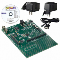
KIT DEV FOR ADUC832 QUICK START
Manufacturer
Analog Devices Inc
Series
QuickStart™ Kitr
Type
MCUr
Specifications of EVAL-ADUC832QSZ
Contents
Evaluation Board, Cable, Power Supply, Software and Documentation
Lead Free Status / RoHS Status
Lead free / RoHS Compliant
For Use With/related Products
ADuC832
Lead Free Status / RoHS Status
Compliant, Lead free / RoHS Compliant
Other names
EVAL-ADUC832QS
EVAL-ADUC832QS
EVAL-ADUC832QS


ADuC832
TIME INTERVAL COUNTER (TIC)
A time interval counter is provided on-chip for counting longer
intervals than the standard 8051 compatible timers are capable
of. The TIC is capable of timeout intervals ranging from 1/128
second to 255 hours. Furthermore, this counter is clocked by
the external 32.768 kHz crystal rather than the core clock and
has the ability to remain active in power-down mode and time
long power-down intervals. This has obvious applications for
remote battery-powered sensors where regular widely spaced
readings are required. Note: Instructions to the TIC SFRs are
also clocked at 32.768 kHz, sufficient time must be allowed for
in user code for these instructions to execute.
Six SFRs are associated with the time interval counter, TIMECON
being its control register. Depending on the configuration of the
IT0 and IT1 bits in TIMECON, the selected time counter register
overflow will clock the interval counter. When this counter is equal
to the time interval value loaded in the INTVAL SFR, the TII bit
(TIMECON.2) is set and generates an interrupt if enabled. If the
ADuC832 is in power-down mode, again with TIC interrupt
enabled, the TII bit will wake up the device and resume code
execution by vectoring directly to the TIC interrupt service vector
address at 0053H. The TIC-related SFRs are described below.
Note also that the timebase SFRs can be written initially with the
current time; the TIC can then be controlled and accessed by
user software. In effect, this facilitates the implementation of a
real-time clock. A block diagram of the TIC is shown in Figure 35.
TIMECON
SFR Address
Power-On Default Value
Bit Addressable
Bit
7
6
5
4
3
2
1
0
Name
----
TFH
ITS1
ITS0
STI
TII
TIEN
TCEN
Description
Reserved for Future Use.
Twenty-Four Hour Select Bit.
Set by the user to enable the Hour counter to count from 0 to 23.
Cleared by the user to enable the Hour counter to count from 0 to 255.
Interval Timebase Selection Bits.
Written by user to determine the interval counter update rate.
ITS1
0
0
1
1
Single Time Interval Bit.
Set by the user to generate a single interval timeout. If set, a timeout will clear the TIEN bit.
Cleared by the user to allow the interval counter to be automatically reloaded and start counting
again at each interval timeout.
TIC Interrupt Bit.
Set when the 8-bit Interval Counter matches the value in the INTVAL SFR.
Cleared by user software.
Time Interval Enable Bit.
Set by the user to enable the 8-bit time interval counter.
Cleared by the user to disable the interval counter.
Time Clock Enable Bit.
Set by the user to enable the time clock to the time interval counters.
Cleared by the user to disable the clock to the time interval counters and reset the time interval
SFRs to the last value written to them by the user. The time registers (HTHSEC, SEC, MIN, and
HOUR) can be written while TCEN is low.
TIC Control Register
A1H
00H
No
Table XVII. TIMECON SFR Bit Designations
ITS0
0
1
0
1
Interval Timebase
1/128 Second
Seconds
Minutes
Hours
–46–
TIME INTERVAL COUNTER INTERRUPT
TCEN
32.768kHz EXTERNAL CRYSTAL
INTERVAL TIMEOUT
Figure 35. TIC, Simplified Block Diagram
HUNDREDTHS COUNTER
SECOND COUNTER
MINUTE COUNTER
HOUR COUNTER
PRESCALER
HOUR
8-BIT
HTHSEC
SEC
MIN
INTERVAL COUNTER
COUNT = INTVAL
TIMER INTVAL
COMPARE
INTVAL
8-BIT
SELECTION
INTERVAL
TIMEBASE
ITS0, 1
MUX
REV. 0
TIEN
Related parts for EVAL-ADUC832QSZ
Image
Part Number
Description
Manufacturer
Datasheet
Request
R


Part Number:
Description:
BOARD EVAL FOR SI270X-A
Manufacturer:
Silicon Laboratories Inc
Datasheet:

Part Number:
Description:
BUCK CONV REF DESIGN KIT IP1201
Manufacturer:
International Rectifier
Datasheet:
Part Number:
Description:
BOARD DEMO SYNC DUAL BUCK CNVTER
Manufacturer:
International Rectifier
Datasheet:
Part Number:
Description:
BOARD DEMO SYNC BUCK CONVETER
Manufacturer:
International Rectifier
Datasheet:

Part Number:
Description:
EVALBOARD/EB Omnidirectional microphone - Analog
Manufacturer:
Analog Devices
Datasheet:
Part Number:
Description:
EVALBOARD/EB Omnidirectional microphone - Analog
Manufacturer:
Analog Devices
Datasheet:


Part Number:
Description:
BOARD EVAL LED DRIVER LT3756
Manufacturer:
Linear Technology
Datasheet:

Part Number:
Description:
BOARD EVAL FOR AD7741/7742
Manufacturer:
Analog Devices Inc
Datasheet:

Part Number:
Description:
±1.7g Dual-Axis IMEMS Accelerometer Evaluation Board
Manufacturer:
Analog Devices Inc
Datasheet:

Part Number:
Description:
IC MULTIPLIER ANALOG 8-SOIC T/R
Manufacturer:
Analog Devices Inc
Datasheet:

Part Number:
Description:
IC ANALOG MULTIPLIER 8-DIP
Manufacturer:
Analog Devices Inc
Datasheet:
Part Number:
Description:
IC ANALOG MULTIPLIER 8-SOIC
Manufacturer:
Analog Devices Inc
Datasheet:
Part Number:
Description:
IC ANALOG MULTIPLIER 8-DIP
Manufacturer:
Analog Devices Inc
Datasheet: