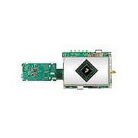
MCIMX35WPDKJ Freescale Semiconductor, MCIMX35WPDKJ Datasheet - Page 121

MCIMX35WPDKJ
Manufacturer Part Number
MCIMX35WPDKJ
Description
BOARD DEV FOR I.MX35
Manufacturer
Freescale Semiconductor
Series
i.MX35r
Type
MPUr
Datasheets
1.MCIMX35WPDKJ.pdf
(148 pages)
2.MCIMX35WPDKJ.pdf
(2 pages)
3.MCIMX35WPDKJ.pdf
(10 pages)
Specifications of MCIMX35WPDKJ
Contents
Module and Misc Hardware
Processor To Be Evaluated
i.MX35
Processor Series
i.MX35
Data Bus Width
32 bit
Interface Type
RS-232, Ethernet, USB, CAN, JTAG
Core
ARM11
For Use With/related Products
i.MX35
Lead Free Status / RoHS Status
Lead free / RoHS Compliant
- Current page: 121 of 148
- Download datasheet (3Mb)
4.9.23
This section describes the electrical information of the UART module.
4.9.23.1
The following subsections give the UART transmit and receive timings in RS-232 serial mode.
4.9.23.1.11 UART Transmitter
Figure 97
Table 79
Freescale Semiconductor
SS25
SS26
SS28
SS30
SS32
SS34
SS35
SS36
SS40
SS41
(output)
ID
TXD
lists the UART RS-232 serial mode transmit timing characteristics.
depicts the transmit timing of UART in RS-232 serial mode, with 8 data bit/1 stop bit format.
(Tx/Rx) CK clock low period
(Tx/Rx) CK clock fall time
(Rx) CK high to FS (bl) high
(Rx) CK high to FS (bl) low
(Rx) CK high to FS (wl) high
(Rx) CK high to FS (wl) low
(Tx/Rx) External FS rise time
(Tx/Rx) External FS fall time
SRXD setup time before (Rx) CK low
SRXD hold time after (Rx) CK low
UART Electrical
UART RS-232 Serial Mode Timing
Table 78. SSI Receiver with External Clock Timing Parameters (continued)
Start
UA1
Bit
i.MX35 Applications Processors for Industrial and Consumer Products, Rev. 9
Figure 97. UART RS-232 Serial Mode Transmit Timing Diagram
Bit 0
Bit 1
Bit 2
Parameter
Bit 3
UA1
Bit 4
Bit 5
Bit 6
Bit 7
Possible
–10.0
–10.0
Min.
36.0
10.0
10.0
10.0
Par Bit
Parity
2.0
UA1
—
—
—
Bit
STOP
UA1
BIT
Max.
15.0
15.0
6.0
6.0
6.0
—
—
—
—
—
Next
Start
Bit
Unit
ns
ns
ns
ns
ns
ns
ns
ns
ns
ns
121
Related parts for MCIMX35WPDKJ
Image
Part Number
Description
Manufacturer
Datasheet
Request
R
Part Number:
Description:
MCIMX-LVDS1
Manufacturer:
Freescale Semiconductor
Datasheet:
Part Number:
Description:
Manufacturer:
Freescale Semiconductor, Inc
Datasheet:
Part Number:
Description:
Manufacturer:
Freescale Semiconductor, Inc
Datasheet:
Part Number:
Description:
Manufacturer:
Freescale Semiconductor, Inc
Datasheet:
Part Number:
Description:
Manufacturer:
Freescale Semiconductor, Inc
Datasheet:
Part Number:
Description:
Manufacturer:
Freescale Semiconductor, Inc
Datasheet:
Part Number:
Description:
Manufacturer:
Freescale Semiconductor, Inc
Datasheet:
Part Number:
Description:
Manufacturer:
Freescale Semiconductor, Inc
Datasheet:
Part Number:
Description:
Manufacturer:
Freescale Semiconductor, Inc
Datasheet:
Part Number:
Description:
Manufacturer:
Freescale Semiconductor, Inc
Datasheet:
Part Number:
Description:
Manufacturer:
Freescale Semiconductor, Inc
Datasheet:
Part Number:
Description:
Manufacturer:
Freescale Semiconductor, Inc
Datasheet:
Part Number:
Description:
Manufacturer:
Freescale Semiconductor, Inc
Datasheet:
Part Number:
Description:
Manufacturer:
Freescale Semiconductor, Inc
Datasheet:
Part Number:
Description:
Manufacturer:
Freescale Semiconductor, Inc
Datasheet:


