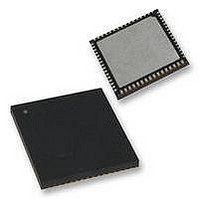
PIC18F65K90T-I/MR Microchip Technology, PIC18F65K90T-I/MR Datasheet - Page 283

PIC18F65K90T-I/MR
Manufacturer Part Number
PIC18F65K90T-I/MR
Description
32kB Flash, 2kB RAM, 1kB EE, NanoWatt XLP, LCD 64 QFN 9x9x0.9mm T/R
Manufacturer
Microchip Technology
Series
PIC® XLP™ 18Fr
Datasheet
1.PIC18F66K90-IMR.pdf
(570 pages)
Specifications of PIC18F65K90T-I/MR
Processor Series
PIC18F
Core
PIC
Data Bus Width
8 bit
Program Memory Type
Flash
Program Memory Size
32 KB
Data Ram Size
2 KB
Interface Type
I2C, SPI
Maximum Clock Frequency
64 MHz
Number Of Timers
8
Operating Supply Voltage
1.8 V to 5.5 V
Maximum Operating Temperature
+ 125 C
3rd Party Development Tools
52715-96, 52716-328, 52717-734, 52712-325, EWPIC18
Minimum Operating Temperature
- 40 C
On-chip Adc
12 bit, 16 Channel
Core Processor
PIC
Core Size
8-Bit
Speed
64MHz
Connectivity
I²C, LIN, SPI, UART/USART
Peripherals
Brown-out Detect/Reset, LCD, POR, PWM, WDT
Number Of I /o
53
Eeprom Size
1K x 8
Ram Size
2K x 8
Voltage - Supply (vcc/vdd)
1.8 V ~ 5.5 V
Data Converters
A/D 16x12b
Oscillator Type
Internal
Operating Temperature
-40°C ~ 85°C
Package / Case
64-VFQFN Exposed Pad
Lead Free Status / Rohs Status
Details
- Current page: 283 of 570
- Download datasheet (5Mb)
There are two power modes designated as “Mode A”
and “Mode B”. Mode A is set by the bits, LRLAP<1:0>
and Mode B by LRLB<1:0>. The resistor ladder to use
for Modes A and B are selected by the bits,
LRLAP<1:0> and LRLBP<1:0>, respectively
Each ladder has a matching contrast control ladder,
tuned to the nominal resistance of the reference ladder.
This contrast control resistor can be controlled by
LCDREF<5:3> (LCDCST<2:0>). Disabling the internal
reference ladder results in all of the ladders being
disconnected, allowing external voltages to be
supplied.
To get additional current in High-Power mode, when
LCDRL<7:6> (LRLAP<1:0>) = 11, both the medium
and high-power resistor ladders are activated.
Whenever the LCD module is inactive (LCDA
(LCDPS<5>) = 0), the reference ladder will be turned
off.
FIGURE 20-5:
2009-2011 Microchip Technology Inc.
Segment Data
LRLAT<2:0>
Power Mode
lcd_32x_clk
cnt<4:0>
lcd_clk
'H00
LCD REFERENCE LADDER POWER MODE SWITCHING DIAGRAM
Power Mode A
LRLAT<2:0>
'H01
'H02
'H03
Single Segment Time
'H04
'H05
PIC18F87K90 FAMILY
20.3.2.1
As an LCD segment is electrically only a capacitor, cur-
rent is drawn only during the interval when the voltage
is switching. To minimize total device current, the LCD
reference ladder can be operated in a different power
mode for the transition portion of the duration. This is
controlled by the LCDRL register.
Mode A Power mode is active for a programmable time,
beginning at the time when the LCD segment waveform
is transitioning. The LCDRL<2:1> (LRLAT<2:0>) bits
select how long, or if the Mode A is active. Mode B
Power mode is active for the remaining time before the
segments or commons change again.
As shown in
segment time. Type-A can be chosen during the time
when the wave form is in transition. Type-B can be
used when the clock is stable or not in transition.
By using this feature of automatic power switching,
using Type-A/Type-B, the power consumption can be
optimized for a given contrast.
'H3
Power Mode B
'H06
'H07
Figure
Automatic Power Mode Switching
20-5, there are 32 counts in a single
'H1E
'H1F
DS39957D-page 283
'H00
Mode A
'H01
Related parts for PIC18F65K90T-I/MR
Image
Part Number
Description
Manufacturer
Datasheet
Request
R

Part Number:
Description:
Manufacturer:
Microchip Technology Inc.
Datasheet:

Part Number:
Description:
Manufacturer:
Microchip Technology Inc.
Datasheet:

Part Number:
Description:
Manufacturer:
Microchip Technology Inc.
Datasheet:

Part Number:
Description:
Manufacturer:
Microchip Technology Inc.
Datasheet:

Part Number:
Description:
Manufacturer:
Microchip Technology Inc.
Datasheet:

Part Number:
Description:
Manufacturer:
Microchip Technology Inc.
Datasheet:

Part Number:
Description:
Manufacturer:
Microchip Technology Inc.
Datasheet:

Part Number:
Description:
Manufacturer:
Microchip Technology Inc.
Datasheet:


