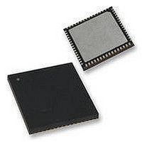
PIC18F65K90T-I/MR Microchip Technology, PIC18F65K90T-I/MR Datasheet - Page 557

PIC18F65K90T-I/MR
Manufacturer Part Number
PIC18F65K90T-I/MR
Description
32kB Flash, 2kB RAM, 1kB EE, NanoWatt XLP, LCD 64 QFN 9x9x0.9mm T/R
Manufacturer
Microchip Technology
Series
PIC® XLP™ 18Fr
Datasheet
1.PIC18F66K90-IMR.pdf
(570 pages)
Specifications of PIC18F65K90T-I/MR
Processor Series
PIC18F
Core
PIC
Data Bus Width
8 bit
Program Memory Type
Flash
Program Memory Size
32 KB
Data Ram Size
2 KB
Interface Type
I2C, SPI
Maximum Clock Frequency
64 MHz
Number Of Timers
8
Operating Supply Voltage
1.8 V to 5.5 V
Maximum Operating Temperature
+ 125 C
3rd Party Development Tools
52715-96, 52716-328, 52717-734, 52712-325, EWPIC18
Minimum Operating Temperature
- 40 C
On-chip Adc
12 bit, 16 Channel
Core Processor
PIC
Core Size
8-Bit
Speed
64MHz
Connectivity
I²C, LIN, SPI, UART/USART
Peripherals
Brown-out Detect/Reset, LCD, POR, PWM, WDT
Number Of I /o
53
Eeprom Size
1K x 8
Ram Size
2K x 8
Voltage - Supply (vcc/vdd)
1.8 V ~ 5.5 V
Data Converters
A/D 16x12b
Oscillator Type
Internal
Operating Temperature
-40°C ~ 85°C
Package / Case
64-VFQFN Exposed Pad
Lead Free Status / Rohs Status
Details
- Current page: 557 of 570
- Download datasheet (5Mb)
Core Features
CPFSEQ ........................................................................... 468
CPFSGT ........................................................................... 469
CPFSLT ............................................................................ 469
Crystal Oscillator/Ceramic Resonators (HS)....................... 46
Customer Change Notification Service ............................. 566
Customer Notification Service........................................... 566
Customer Support............................................................. 566
D
Data Addressing Modes.................................................... 104
Data EEPROM Memory
Data Memory ...................................................................... 92
Data Memory Modes
DAW.................................................................................. 470
DC Characteristics
DCFSNZ ........................................................................... 471
DECF ................................................................................ 470
DECFSZ............................................................................ 471
Default System Clock.......................................................... 46
Details on Individual Family Members ................................ 10
Development Support ....................................................... 501
Device Overview ................................................................... 9
Direct Addressing.............................................................. 105
2009-2011 Microchip Technology Inc.
Easy Migration .............................................................. 9
Extended Instruction Set............................................... 9
Memory Options............................................................ 9
nanoWatt Technology ................................................... 9
Oscillator Options and Features ................................... 9
Comparing Addressing Modes (Bit-Oriented,
Direct......................................................................... 104
Indexed Literal Offset
Indirect ...................................................................... 104
Inherent and Literal ................................................... 104
Associated Registers ................................................ 125
EEADR and EEADRH Registers .............................. 121
EECON1 and EECON2 Registers ............................ 121
Operation During Code-Protect ................................ 124
Overview ................................................................... 121
Protection, Spurious Writes ...................................... 124
Reading..................................................................... 123
Usage........................................................................ 124
Write Verify ............................................................... 123
Writing To.................................................................. 123
Access Bank ............................................................... 94
Bank Select Register (BSR)........................................ 92
Extended Instruction Set........................................... 107
General Purpose Registers......................................... 94
Memory Maps
Special Function Registers ......................................... 95
Indexed Literal Offset................................................ 107
CTMU Current Source .............................................. 520
PIC18F87K90 Family, Industrial ............................... 519
Power-Down and Supply Current ............................. 508
Supply Voltage.......................................................... 507
Features (64-Pin Devices) .......................................... 11
Features (80-Pin Devices) .......................................... 11
Byte Oriented) with the Extended
Instruction Set Enabled..................................... 108
BSR .................................................................. 109
Mapping Access Bank ...................................... 109
PIC18FX5K90/X7K90 Devices ........................... 93
Special Function Registers ................................. 95
Affected Instructions ......................................... 107
PIC18F87K90 FAMILY
E
Effect on Standard PIC18 Instructions.............................. 498
Effects of Power-Managed Modes on Various
Electrical Characteristics .................................................. 505
Enhanced Capture/Compare/PWM (ECCP)..................... 251
Enhanced Capture/Compare/PWM (ECCP1/2/3)
Enhanced Universal Synchronous Asynchronous Receiver
Equations
EUSART
Clock Sources ............................................................ 52
Capture Mode. See Capture.
Compare Mode. See Compare.
ECCP Mode and Timer Resources .......................... 254
Enhanced PWM Mode.............................................. 257
Outputs and Configuration........................................ 254
Associated Registers................................................ 272
Transmitter (EUSART). See EUSART.
16 x 16 Signed Multiplication Algorithm.................... 128
16 x 16 Unsigned Multiplication Algorithm................ 128
A/D Acquisition Time ................................................ 384
A/D Minimum Charging Time ................................... 384
Calculating the Minimum Required
Converting Error Pulses ........................................... 232
Asynchronous Mode................................................. 359
Baud Rate Generator
Baud Rate Generator (BRG) .................................... 353
Synchronous Master Mode....................................... 367
Auto-Restart ..................................................... 266
Auto-Shutdown ................................................. 264
Direction Change in Full-Bridge
Full-Bridge Application...................................... 261
Full-Bridge Mode .............................................. 261
Half-Bridge Application ..................................... 260
Half-Bridge Application Examples .................... 267
Half-Bridge Mode.............................................. 260
Output Relationships (Active-High and
Output Relationships Diagram.......................... 259
Programmable Dead-Band Delay..................... 267
Shoot-Through Current..................................... 267
Start-up Considerations.................................... 264
Acquisition Time ............................................... 384
12-Bit Break Transmit and Receive
Associated Registers, Receive......................... 363
Associated Registers, Transmit........................ 361
Auto-Wake-up on Sync Break .......................... 364
Receiver ........................................................... 362
Setting Up 9-Bit Mode with Address Detect ..... 362
Transmitter ....................................................... 359
Operation in Power-Managed Modes............... 353
Associated Registers........................................ 354
Auto-Baud Rate Detect..................................... 357
Baud Rate Error, Calculating............................ 354
Baud Rates, Asynchronous Modes .................. 355
High Baud Rate Select (BRGH Bit) .................. 353
Sampling .......................................................... 353
Associated Registers, Receive......................... 370
Associated Registers, Transmit........................ 368
Reception ......................................................... 369
Transmission .................................................... 367
Output Mode............................................. 263
Active-Low)............................................... 258
Sequence ................................................. 366
DS39957D-page 557
Related parts for PIC18F65K90T-I/MR
Image
Part Number
Description
Manufacturer
Datasheet
Request
R

Part Number:
Description:
Manufacturer:
Microchip Technology Inc.
Datasheet:

Part Number:
Description:
Manufacturer:
Microchip Technology Inc.
Datasheet:

Part Number:
Description:
Manufacturer:
Microchip Technology Inc.
Datasheet:

Part Number:
Description:
Manufacturer:
Microchip Technology Inc.
Datasheet:

Part Number:
Description:
Manufacturer:
Microchip Technology Inc.
Datasheet:

Part Number:
Description:
Manufacturer:
Microchip Technology Inc.
Datasheet:

Part Number:
Description:
Manufacturer:
Microchip Technology Inc.
Datasheet:

Part Number:
Description:
Manufacturer:
Microchip Technology Inc.
Datasheet:


