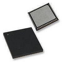
PIC18F65K90-I/MR Microchip Technology, PIC18F65K90-I/MR Datasheet - Page 56

PIC18F65K90-I/MR
Manufacturer Part Number
PIC18F65K90-I/MR
Description
32kB Flash, 2kB RAM, 1kB EE, NanoWatt XLP, LCD 64 QFN 9x9x0.9mm TUBE
Manufacturer
Microchip Technology
Series
PIC® XLP™ 18Fr
Datasheet
1.PIC18F65K90-IMR.pdf
(570 pages)
Specifications of PIC18F65K90-I/MR
Processor Series
PIC18F
Core
PIC
Data Bus Width
8 bit
Program Memory Type
Flash
Program Memory Size
32 KB
Data Ram Size
2 KB
Interface Type
I2C, SPI
Maximum Clock Frequency
64 MHz
Number Of Timers
8
Operating Supply Voltage
1.8 V to 5.5 V
Maximum Operating Temperature
+ 125 C
3rd Party Development Tools
52715-96, 52716-328, 52717-734, 52712-325, EWPIC18
Minimum Operating Temperature
- 40 C
On-chip Adc
12 bit, 16 Channel
Core Processor
PIC
Core Size
8-Bit
Speed
64MHz
Connectivity
I²C, LIN, SPI, UART/USART
Peripherals
Brown-out Detect/Reset, LCD, POR, PWM, WDT
Number Of I /o
53
Eeprom Size
1K x 8
Ram Size
2K x 8
Voltage - Supply (vcc/vdd)
1.8 V ~ 5.5 V
Data Converters
A/D 16x12b
Oscillator Type
Internal
Operating Temperature
-40°C ~ 85°C
Package / Case
64-VFQFN Exposed Pad
Lead Free Status / Rohs Status
Details
- Current page: 56 of 570
- Download datasheet (5Mb)
PIC18F87K90 FAMILY
If the IRCF bits and the INTSRC bit are all clear, the
INTOSC output (HF-INTOSC/MF-INTOSC) is not
enabled, and the HFIOFS and MFIOFS bits will remain
clear. There will be no indication of the current clock
source. The LF-INTOSC source is providing the device
clocks.
TABLE 4-3:
Clocks to the device continue while the INTOSC source
stabilizes after an interval of T
Table
If the IRCF bits were previously at a non-zero value, or
if INTSRC was set before setting SCS1, and the
INTOSC source was already stable, the HFIOFS or
MFIOFS bit will remain set.
DS39957D-page 56
IRCF<2:0>
Non-Zero
Non-Zero
31-10).
000
000
000
INTERNAL OSCILLATOR FREQUENCY STABILITY BITS
INTSRC
0
1
1
x
x
IOBST
(Parameter 39,
MFIOSEL
x
0
1
0
1
MFIOFS = 0, HFIOFS = 0 and clock source is LF-INTOSC
MFIOFS = 0, HFIOFS = 1 and clock source is HF-INTOSC
MFIOFS = 1, HFIOFS = 0 and clock source is MF-INTOSC
MFIOFS = 0, HFIOFS = 1 and clock source is HF-INTOSC
MFIOFS = 1, HFIOFS = 0 and clock source is MF-INTOSC
Status of MFIOFS or HFIOFS when INTOSC is Stable
If the IRCF bits are changed from all clear (thus,
enabling the INTOSC output) or if INTSRC or
MFIOSEL is set, the HFIOFS or MFIOFS bit is set after
the INTOSC output becomes stable. For details, see
Table
On transitions from RC_RUN mode to PRI_RUN mode,
the device continues to be clocked from the INTOSC
multiplexer while the primary clock is started. When the
primary clock becomes ready, a clock switch to the
primary clock occurs (see
switch is complete, the HFIOFS or MFIOFS bit is
cleared, the OSTS bit is set and the primary clock is
providing the device clock. The IDLEN and SCS bits
are not affected by the switch. The LF-INTOSC source
will continue to run if either the WDT or the Fail-Safe
Clock Monitor is enabled.
4-3.
2009-2011 Microchip Technology Inc.
Figure
4-4). When the clock
Related parts for PIC18F65K90-I/MR
Image
Part Number
Description
Manufacturer
Datasheet
Request
R

Part Number:
Description:
Manufacturer:
Microchip Technology Inc.
Datasheet:

Part Number:
Description:
Manufacturer:
Microchip Technology Inc.
Datasheet:

Part Number:
Description:
Manufacturer:
Microchip Technology Inc.
Datasheet:

Part Number:
Description:
Manufacturer:
Microchip Technology Inc.
Datasheet:

Part Number:
Description:
Manufacturer:
Microchip Technology Inc.
Datasheet:

Part Number:
Description:
Manufacturer:
Microchip Technology Inc.
Datasheet:

Part Number:
Description:
Manufacturer:
Microchip Technology Inc.
Datasheet:

Part Number:
Description:
Manufacturer:
Microchip Technology Inc.
Datasheet:


