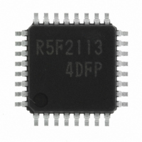
R5F21134DFP#U0 Renesas Electronics America, R5F21134DFP#U0 Datasheet - Page 61

R5F21134DFP#U0
Manufacturer Part Number
R5F21134DFP#U0
Description
IC R8C MCU FLASH 32LQFP
Manufacturer
Renesas Electronics America
Series
M16C™ M16C/R8C/Tiny/13r
Datasheets
1.R5F211A2SPU0.pdf
(300 pages)
2.R5F21132FPU0.pdf
(33 pages)
3.R5F21132FPU0.pdf
(226 pages)
4.R5F21134DFPU0.pdf
(224 pages)
Specifications of R5F21134DFP#U0
Core Size
16-Bit
Program Memory Size
16KB (16K x 8)
Oscillator Type
Internal
Core Processor
R8C
Speed
20MHz
Connectivity
SIO, UART/USART
Peripherals
LED, POR, Voltage Detect, WDT
Number Of I /o
22
Program Memory Type
FLASH
Ram Size
1K x 8
Voltage - Supply (vcc/vdd)
2.7 V ~ 5.5 V
Data Converters
A/D 12x10b
Operating Temperature
-40°C ~ 85°C
Package / Case
32-LQFP
No. Of I/o's
22
Eeprom Memory Size
4KB
Ram Memory Size
1024Byte
Cpu Speed
20MHz
No. Of Timers
16
Digital Ic Case
RoHS Compliant
Controller Family/series
R8C/13
Rohs Compliant
Yes
Lead Free Status / RoHS Status
Lead free / RoHS Compliant
For Use With
R0K521134S000BE - KIT EVAL STARTER FOR R8C/13R0E521134EPB00 - KIT EMULATOR PROBE FOR PC7501R0E521134CPE00 - EMULATOR COMPACT R8C/13
Eeprom Size
-
Lead Free Status / RoHS Status
Lead free / RoHS Compliant
Available stocks
Company
Part Number
Manufacturer
Quantity
Price
Part Number:
R5F21134DFP#U0R5F21134DFP
Manufacturer:
Renesas Electronics America
Quantity:
10 000
- R5F211A2SPU0 PDF datasheet
- R5F21132FPU0 PDF datasheet #2
- R5F21132FPU0 PDF datasheet #3
- R5F21134DFPU0 PDF datasheet #4
- Current page: 61 of 224
- Download datasheet (3Mb)
R8C/13 Group
Rev.1.20
REJ09B0111-0120
Figure 10.2 Interrupt Vector
Table 10.1 Fixed Vector Tables
NOTES:
Interrupt factor
Undefined instruction 0FFDC
Overflow
BRK instruction
Address match
Single step
• Watchdog timer
• Oscillation stop
• Voltage detection
(Reserved)
(Reserved)
Reset
1. Do not normally use this interrupt because it is provided exclusively for use by development support tools.
detection
10.1.4 Interrupts and Interrupt Vector
One interrupt vector consists of 4 bytes. Set the start address of each interrupt routine in the respec-
tive interrupt vectors. When an interrupt request is accepted, the CPU branches to the address set in
the corresponding interrupt vector. Figure 10.2 shows the interrupt vector.
• Fixed Vector Tables
Jan 27, 2006
The fixed vector tables are allocated to the addresses from 0FFDC
the fixed vector tables. In the flash memory version of microcomputer, the vector addresses (H) of
fixed vectors are used by the ID code check function. For details, refer to Section 17.3, “Functions to
Prevent Flash Memory from Rewriting.”
(1)
V e c t o r a d d r e s s ( H )
V e c t o r a d d r e s s ( L )
page 50 of 205
Address (L) to address (H)
NOTES:
0FFEC
0FFE8
0FFFC
0FFE0
0FFE4
0FFF8
0FFF0
0FFF4
1. The OFS register is assigned to the 0FFFF16 address. Refer to "Figure11.2
Vector addresses
OFS, WDC, WDTR and WDTS registers" for the OFS register details.
16
16
16
16
16
16
16
16
16
to 0FFEB
to 0FFFB
to 0FFE3
to 0FFE7
to 0FFF3
to 0FFF7
to 0FFDF
to 0FFEF
to 0FFFF
MSB
16
16
16
16
16
16
16
16
16
0 0 0 0
0 0 0 0
If the contents of address
0FFE7
ecution starts from the address
shown by the vector in the
relocatable vector table.
Interrupt on UND instruction
Interrupt on INTO instruction
Low address
Mid address
16
High address
is FF
Remarks
0 0 0 0
16
, program ex-
L S B
( N o t e 1 )
16
to 0FFFF
R8C/Tiny Series
software manual
18.1 Address match
11. Watchdog timer
6. Clock generation
5.4Voltage detection
Reset
10.1 Interrupt Overview
circuit
circuit
interrupt
16
Reference
. Table 10.1 lists
Related parts for R5F21134DFP#U0
Image
Part Number
Description
Manufacturer
Datasheet
Request
R

Part Number:
Description:
KIT STARTER FOR M16C/29
Manufacturer:
Renesas Electronics America
Datasheet:

Part Number:
Description:
KIT STARTER FOR R8C/2D
Manufacturer:
Renesas Electronics America
Datasheet:

Part Number:
Description:
R0K33062P STARTER KIT
Manufacturer:
Renesas Electronics America
Datasheet:

Part Number:
Description:
KIT STARTER FOR R8C/23 E8A
Manufacturer:
Renesas Electronics America
Datasheet:

Part Number:
Description:
KIT STARTER FOR R8C/25
Manufacturer:
Renesas Electronics America
Datasheet:

Part Number:
Description:
KIT STARTER H8S2456 SHARPE DSPLY
Manufacturer:
Renesas Electronics America
Datasheet:

Part Number:
Description:
KIT STARTER FOR R8C38C
Manufacturer:
Renesas Electronics America
Datasheet:

Part Number:
Description:
KIT STARTER FOR R8C35C
Manufacturer:
Renesas Electronics America
Datasheet:

Part Number:
Description:
KIT STARTER FOR R8CL3AC+LCD APPS
Manufacturer:
Renesas Electronics America
Datasheet:

Part Number:
Description:
KIT STARTER FOR RX610
Manufacturer:
Renesas Electronics America
Datasheet:

Part Number:
Description:
KIT STARTER FOR R32C/118
Manufacturer:
Renesas Electronics America
Datasheet:

Part Number:
Description:
KIT DEV RSK-R8C/26-29
Manufacturer:
Renesas Electronics America
Datasheet:

Part Number:
Description:
KIT STARTER FOR SH7124
Manufacturer:
Renesas Electronics America
Datasheet:

Part Number:
Description:
KIT STARTER FOR H8SX/1622
Manufacturer:
Renesas Electronics America
Datasheet:

Part Number:
Description:
KIT DEV FOR SH7203
Manufacturer:
Renesas Electronics America
Datasheet:


