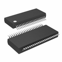
ATMEGA32HVB-8X3 Atmel, ATMEGA32HVB-8X3 Datasheet - Page 124

ATMEGA32HVB-8X3
Manufacturer Part Number
ATMEGA32HVB-8X3
Description
MCU AVR 32KB FLASH 8MHZ 44TSSOP
Manufacturer
Atmel
Series
AVR® ATmegar
Specifications of ATMEGA32HVB-8X3
Core Processor
AVR
Core Size
8-Bit
Speed
8MHz
Connectivity
I²C, SPI
Peripherals
POR, WDT
Number Of I /o
17
Program Memory Size
32KB (16K x 16)
Program Memory Type
FLASH
Eeprom Size
1K x 8
Ram Size
2K x 8
Voltage - Supply (vcc/vdd)
4 V ~ 25 V
Data Converters
A/D 7x12b
Oscillator Type
External
Operating Temperature
-40°C ~ 85°C
Package / Case
44-TSSOP
Processor Series
ATMEGA32x
Core
AVR8
Data Bus Width
8 bit
Data Ram Size
2 KB
Interface Type
SPI, TWI
Maximum Clock Frequency
8 MHz
Number Of Programmable I/os
17
Number Of Timers
2
Maximum Operating Temperature
+ 85 C
Mounting Style
SMD/SMT
Development Tools By Supplier
ATAVRDRAGON, ATSTK500, ATSTK600, ATAVRISP2, ATAVRONEKIT, ATAVRSB200
Minimum Operating Temperature
- 40 C
On-chip Adc
12 bit, 7 Channel
Package
44TSSOP
Device Core
AVR
Family Name
ATmega
Maximum Speed
8 MHz
Operating Supply Voltage
5|9|12|15|18|24 V
For Use With
ATSTK524 - KIT STARTER ATMEGA32M1/MEGA32C1ATSTK600 - DEV KIT FOR AVR/AVR32ATAVRDRAGON - KIT DRAGON 32KB FLASH MEM AVRATSTK500 - PROGRAMMER AVR STARTER KIT
Lead Free Status / RoHS Status
Lead free / RoHS Compliant
Available stocks
Company
Part Number
Manufacturer
Quantity
Price
Company:
Part Number:
ATMEGA32HVB-8X3
Manufacturer:
Atmel
Quantity:
408
21.3
21.4
21.5
8042B–AVR–06/10
Operation
Bandgap Calibration
Bandgap Buffer Settling Time
When the device is in power-off state, the Voltage Reference will be switched off. After a Power-
on reset condition the Voltage Reference will automatically be enabled.
By default the Bandgap Buffer will be enabled as the buffered reference voltage is used as refer-
ence for the Battery Protection, the internal Cell Balancing, the V-ADC and the CC-ADC. If any
of these modules are enabled the Bandgap Buffer must be enabled, otherwise it is recom-
mended to disable the buffer by writing to the BGD bit in BGCSR to save power. Note that the
Bandgap Buffer needs settling time before the voltage is stable. For details on settling time, see
”Bandgap Buffer Settling Time” on page
To ensure that the battery protection has safe operation condition, the Voltage Reference
includes a Short-circuit Detector. The Bandgap Short Detector continuously monitors the internal
1.100V reference voltage against the VREF pin voltage to detect potentially external short condi-
tions to VCC or GND. If an external short condition is detected, the Bandgap Short Circuit
Detection is capable of interrupting and waking up the CPU from any sleep mode. If a Bandgap
Short-circuit condition occurs software should immediately disable the C-FET and D-FET. If no
external protection is provided to detect such a condition it is recommended to always enable
this feature, by setting the BGSCDE bit in the Bandgap Control and Status Register.
The Temperature Sensor generates a voltage Proportional-To-Absolute-Temperature, VPTAT.
This voltage is connected to the multiplexer at the V-ADC input and it can be used for runtime
compensation of temperature drift in both the voltage reference and the On-chip Oscillator. To
get the absolute temperature in degrees Kelvin, the measured VPTAT voltage must be scaled
with the VPTAT factory calibration value stored in the signature row. See
Row from Software” on page 199
details on temperature accuracy.
To guarantee ultra low temperature drift the Voltage Reference includes two calibration registers
that should be initialized by software after reset. See
page 126
of the Bandgap Reference Voltage, while changing values to the BGCRR IO register trims the
temperature gradient of the bandgap reference.
When the calibration registers are changed it will affect both the Voltage Regulator output and
BOD-level. The BOD will react quickly to new detection levels, while the regulator will adjust the
voltage more slowly, depending on the size of the external decoupling capacitor. To avoid that a
BOD-reset is issued when calibration is done, it is recommended to change the values of the
BGCC and BGCR bits stepwise, with a step size of 1, and with a hold-off time between each
step. See
Changing VREF will influence the conversion results for the V-ADC and CC-ADC. It is therefore
not recommended to do V-ADC and CC-ADC conversions while calibrating the bandgap.
After the Voltage Reference have been enabled it needs a settling time before the voltage is sta-
ble. The settling time depends on the size of the external decoupling capacitor. With 1 µF
external capacitor a minimum settling time of 2ms should be used. Until settling is done it is not
for details. Changing values to the BGCCR IO register will change the nominal value
”Electrical Characteristics” on page 230
for details.
124.
See”Electrical Characteristics” on page 230
for details on hold-off time.
ATmega16HVB/32HVB
Section 21.6 ”Register Description” on
”Reading the Signature
124
for


