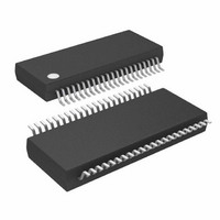
ATMEGA32HVB-8X3 Atmel, ATMEGA32HVB-8X3 Datasheet - Page 37

ATMEGA32HVB-8X3
Manufacturer Part Number
ATMEGA32HVB-8X3
Description
MCU AVR 32KB FLASH 8MHZ 44TSSOP
Manufacturer
Atmel
Series
AVR® ATmegar
Specifications of ATMEGA32HVB-8X3
Core Processor
AVR
Core Size
8-Bit
Speed
8MHz
Connectivity
I²C, SPI
Peripherals
POR, WDT
Number Of I /o
17
Program Memory Size
32KB (16K x 16)
Program Memory Type
FLASH
Eeprom Size
1K x 8
Ram Size
2K x 8
Voltage - Supply (vcc/vdd)
4 V ~ 25 V
Data Converters
A/D 7x12b
Oscillator Type
External
Operating Temperature
-40°C ~ 85°C
Package / Case
44-TSSOP
Processor Series
ATMEGA32x
Core
AVR8
Data Bus Width
8 bit
Data Ram Size
2 KB
Interface Type
SPI, TWI
Maximum Clock Frequency
8 MHz
Number Of Programmable I/os
17
Number Of Timers
2
Maximum Operating Temperature
+ 85 C
Mounting Style
SMD/SMT
Development Tools By Supplier
ATAVRDRAGON, ATSTK500, ATSTK600, ATAVRISP2, ATAVRONEKIT, ATAVRSB200
Minimum Operating Temperature
- 40 C
On-chip Adc
12 bit, 7 Channel
Package
44TSSOP
Device Core
AVR
Family Name
ATmega
Maximum Speed
8 MHz
Operating Supply Voltage
5|9|12|15|18|24 V
For Use With
ATSTK524 - KIT STARTER ATMEGA32M1/MEGA32C1ATSTK600 - DEV KIT FOR AVR/AVR32ATAVRDRAGON - KIT DRAGON 32KB FLASH MEM AVRATSTK500 - PROGRAMMER AVR STARTER KIT
Lead Free Status / RoHS Status
Lead free / RoHS Compliant
Available stocks
Company
Part Number
Manufacturer
Quantity
Price
Company:
Part Number:
ATMEGA32HVB-8X3
Manufacturer:
Atmel
Quantity:
408
- Current page: 37 of 275
- Download datasheet (7Mb)
Table 10-2.
Notes:
10.2
10.3
10.4
8042B–AVR–06/10
Module
External Interrupts
Battery Protection
Watchdog Timer
Voltage Regulator
Bandgap Reference
FET Driver
CHARGER_DETECT
1. Runs only when CC-ADC is enabled, or OSI is enabled and RCOSC_SLOW is selected as source for OSI.
2. Runs only when CC-ADC is enabled
3. Address Match and Bus Connect/Disconnect Wake-up only
4. Discharge FET must be switched off for Charger Detect to be enabled.
5. VREGMON interrupt (Regulator Operation Condition Warning) not available.
Idle Mode
ADC Noise Reduction
Power-save Mode
Active modules in different Sleep Modes (Continued)
(4)
When the SM2:0 bits are written to 000, the SLEEP instruction makes the MCU enter Idle mode,
stopping the CPU but allowing all peripheral functions to continue operating. This sleep mode
basically halts clk
MCU to wake up from external triggered interrupts as well as internal ones like the Timer Over-
flow interrupt.
When the SM2:0 bits are written to 001, the SLEEP instruction makes the MCU enter ADC
Noise Reduction mode, stopping the CPU but allowing the Voltage ADC (V-ADC), Voltage Reg-
ulator Monitor (VREGMON), Watchdog Timer (WDT), Coulomb Counter (CC), Current Battery
Protection (CBP), Slow RC Oscillator (RCOSC_SLOW) (if CC is enabled), and the Ultra Low
Power RC Oscillator (RCOSC_ULP) to continue operating. This sleep mode basically halts
clk
This improves the noise environment for the Voltage ADC, enabling higher accuracy on
measurements.
When the SM2:0 bits are written to 011, the SLEEP instruction makes the MCU enter Power-
save mode. In this mode, the internal Fast RC Oscillator (RCOSC_FAST) is stopped, while
Watchdog Timer (WDT), Coulomb Counter (CC), Current Battery Protection (CBP) , Slow RC
Oscillator (RCOSC_SLOW) (if CC is enabled), and the Ultra Low Power RC Oscillator
(RCOSC_ULP) continue operating.
This mode will be the default mode when application software does not require operation of
CPU, Flash or any of the peripheral units running at the Fast internal Oscillator (RCOSC_FAST).
I/O
, clk
CPU
Active
, and clk
X
X
X
X
X
X
X
CPU
FLASH
and clk
, while allowing the other clocks to run.
FLASH
Idle
X
X
X
X
X
X
X
, while allowing the other clocks to run. Idle mode enables the
ADC Noise
Reduction
Mode
X
X
X
X
X
X
X
ATmega16HVB/32HVB
Power-save
X
X
X
X
X
X
X
(5)
Power-off
X
37
Related parts for ATMEGA32HVB-8X3
Image
Part Number
Description
Manufacturer
Datasheet
Request
R

Part Number:
Description:
Manufacturer:
Atmel Corporation
Datasheet:

Part Number:
Description:
Manufacturer:
ATMEL Corporation
Datasheet:

Part Number:
Description:
IC AVR MCU 32K 16MHZ 5V 44-QFN
Manufacturer:
Atmel
Datasheet:

Part Number:
Description:
IC AVR MCU 32K 16MHZ 5V 40DIP
Manufacturer:
Atmel
Datasheet:

Part Number:
Description:
IC AVR MCU 32K 16MHZ 5V 44TQFP
Manufacturer:
Atmel
Datasheet:

Part Number:
Description:
IC AVR MCU 32K 16MHZ IND 40-DIP
Manufacturer:
Atmel
Datasheet:

Part Number:
Description:
IC AVR MCU 32K 16MHZ IND 44-TQFP
Manufacturer:
Atmel
Datasheet:

Part Number:
Description:
MCU AVR 32KB FLASH 16MHZ 44TQFP
Manufacturer:
Atmel
Datasheet:

Part Number:
Description:
MCU AVR 32KB FLASH 16MHZ 44QFN
Manufacturer:
Atmel
Datasheet:

Part Number:
Description:
MCU AVR 32K FLASH 16MHZ 44-TQFP
Manufacturer:
Atmel
Datasheet:

Part Number:
Description:
IC AVR MCU 32K 16MHZ COM 40-DIP
Manufacturer:
Atmel
Datasheet:

Part Number:
Description:
IC AVR MCU 32K 16MHZ COM 44-QFN
Manufacturer:
Atmel
Datasheet:

Part Number:
Description:
IC AVR MCU 32K 16MHZ COM 44-TQFP
Manufacturer:
Atmel
Datasheet:


