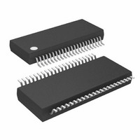
ATMEGA32HVB-8X3 Atmel, ATMEGA32HVB-8X3 Datasheet - Page 31

ATMEGA32HVB-8X3
Manufacturer Part Number
ATMEGA32HVB-8X3
Description
MCU AVR 32KB FLASH 8MHZ 44TSSOP
Manufacturer
Atmel
Series
AVR® ATmegar
Specifications of ATMEGA32HVB-8X3
Core Processor
AVR
Core Size
8-Bit
Speed
8MHz
Connectivity
I²C, SPI
Peripherals
POR, WDT
Number Of I /o
17
Program Memory Size
32KB (16K x 16)
Program Memory Type
FLASH
Eeprom Size
1K x 8
Ram Size
2K x 8
Voltage - Supply (vcc/vdd)
4 V ~ 25 V
Data Converters
A/D 7x12b
Oscillator Type
External
Operating Temperature
-40°C ~ 85°C
Package / Case
44-TSSOP
Processor Series
ATMEGA32x
Core
AVR8
Data Bus Width
8 bit
Data Ram Size
2 KB
Interface Type
SPI, TWI
Maximum Clock Frequency
8 MHz
Number Of Programmable I/os
17
Number Of Timers
2
Maximum Operating Temperature
+ 85 C
Mounting Style
SMD/SMT
Development Tools By Supplier
ATAVRDRAGON, ATSTK500, ATSTK600, ATAVRISP2, ATAVRONEKIT, ATAVRSB200
Minimum Operating Temperature
- 40 C
On-chip Adc
12 bit, 7 Channel
Package
44TSSOP
Device Core
AVR
Family Name
ATmega
Maximum Speed
8 MHz
Operating Supply Voltage
5|9|12|15|18|24 V
For Use With
ATSTK524 - KIT STARTER ATMEGA32M1/MEGA32C1ATSTK600 - DEV KIT FOR AVR/AVR32ATAVRDRAGON - KIT DRAGON 32KB FLASH MEM AVRATSTK500 - PROGRAMMER AVR STARTER KIT
Lead Free Status / RoHS Status
Lead free / RoHS Compliant
Available stocks
Company
Part Number
Manufacturer
Quantity
Price
Company:
Part Number:
ATMEGA32HVB-8X3
Manufacturer:
Atmel
Quantity:
408
9.7.3
8042B–AVR–06/10
Usage
The Slow RC oscillator represents a highly predictable and accurate clock source over the entire
temperature range and provides an excellent reference for calibrating the Fast RC oscillator run-
time. Typically, runtime calibration is needed to provide an accurate Fast RC frequency for
asynchronous serial communication in the complete temperature range.
The Slow RC frequency at 85°C and the Slow RC temperature coefficient are stored in the sig-
nature row. These characteristics can be used to calculate the actual Slow RC clock period at a
given temperature with high precision. Refer to
By measuring the number of CPU cycles of one or more prescaled Slow RC clock periods, the
actual Fast RC oscillator clock period can be determined. The Fast RC clock period can then be
adjusted by writing to the FOSCCAL register. The new Fast RC clock period after calibration
should be verified by repeating the measurement and repeating the calibration if necessary. The
Fast RC clock period as a function of the Slow RC clock period is given by:
where n is the number of prescaled Slow RC periods that is used in the measurement. Using
more prescaled Slow RC periods decreases the measurement error, but increases the time con-
sumed for calibration. Note that the Slow RC Oscillator needs very short time to stabilize after
being enabled by the OSI module. Hence, the calibration algorithm may use the time between
the first and second osi_posedge as time reference for calculations.
Another usage of OSI is determining the ULP frequency accurately. The ULP frequency at 85°C
and the ULP temperature coefficient are stored in the signature row, allowing the ULP frequency
to be calculated directly. However, the ULP frequency is less predictable over temperature than
the Slow RC oscillator frequency, therefore a more accurate result can be obtained by calculat-
ing the ratio between the Slow RC and ULP oscillators. This is done by sampling both the ULP
and Slow RC oscillators and comparing the results. When the ratio is known, the actual ULP fre-
quency can be determined with high accuracy. The ULP RC clock period as a function of the
Slow RC clock period is given by:
where n is the number of prescaled ULP RC and Slow RC periods that is used in the measure-
ment. Using more prescaled ULP RC and Slow RC periods decreases the measurement error,
but increases the time consumed for calibration. Note that the FOSCCAL register must be kept
at a constant value during this operation to ensure accurate results.
These clock period calculations should be performed again when there is a significant change in
die temperature since the previous calculation. The die temperature can be found using the Volt-
age ADC, refer to section
on page 117
for details.
T
T
FastRC
ULPRC
=
=
T
T
SlowRC
SlowRC
”Voltage ADC – 7-channel General Purpose 12-bit Sigma-Delta ADC”
⋅
⋅
------------------------------------------------------------------------------------------------------------------------------------------------ -
number of CPU cycles in n prescaled Slow RC periods
------------------------------------------------------------------------------------------------------------------------------------------------ -
number of CPU cycles in n prescaled Slow RC periods
number of CPU cycles in n prescaled ULP RC periods
”Slow RC Oscillator” on page 27
ATmega16HVB/32HVB
128 n ⋅
for details.
31


