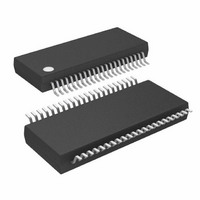
ATMEGA32HVB-8X3 Atmel, ATMEGA32HVB-8X3 Datasheet - Page 130

ATMEGA32HVB-8X3
Manufacturer Part Number
ATMEGA32HVB-8X3
Description
MCU AVR 32KB FLASH 8MHZ 44TSSOP
Manufacturer
Atmel
Series
AVR® ATmegar
Specifications of ATMEGA32HVB-8X3
Core Processor
AVR
Core Size
8-Bit
Speed
8MHz
Connectivity
I²C, SPI
Peripherals
POR, WDT
Number Of I /o
17
Program Memory Size
32KB (16K x 16)
Program Memory Type
FLASH
Eeprom Size
1K x 8
Ram Size
2K x 8
Voltage - Supply (vcc/vdd)
4 V ~ 25 V
Data Converters
A/D 7x12b
Oscillator Type
External
Operating Temperature
-40°C ~ 85°C
Package / Case
44-TSSOP
Processor Series
ATMEGA32x
Core
AVR8
Data Bus Width
8 bit
Data Ram Size
2 KB
Interface Type
SPI, TWI
Maximum Clock Frequency
8 MHz
Number Of Programmable I/os
17
Number Of Timers
2
Maximum Operating Temperature
+ 85 C
Mounting Style
SMD/SMT
Development Tools By Supplier
ATAVRDRAGON, ATSTK500, ATSTK600, ATAVRISP2, ATAVRONEKIT, ATAVRSB200
Minimum Operating Temperature
- 40 C
On-chip Adc
12 bit, 7 Channel
Package
44TSSOP
Device Core
AVR
Family Name
ATmega
Maximum Speed
8 MHz
Operating Supply Voltage
5|9|12|15|18|24 V
For Use With
ATSTK524 - KIT STARTER ATMEGA32M1/MEGA32C1ATSTK600 - DEV KIT FOR AVR/AVR32ATAVRDRAGON - KIT DRAGON 32KB FLASH MEM AVRATSTK500 - PROGRAMMER AVR STARTER KIT
Lead Free Status / RoHS Status
Lead free / RoHS Compliant
Available stocks
Company
Part Number
Manufacturer
Quantity
Price
Company:
Part Number:
ATMEGA32HVB-8X3
Manufacturer:
Atmel
Quantity:
408
22.3
22.3.1
22.3.2
8042B–AVR–06/10
Operation
Device operating state
Interrupt logic
The Charger Detect module is supplied directly from the VFET pin. When operating, the Charger
Detect will monitor the voltage of the BATT pin and detect whether a charger is present or not.
When the voltage on the BATT pin is above the Charger Detect Threshold level V
Characteristics” on page
detected to generate interrupt when a charger is connected or disconnected.
The Charger Detect module will operate as long as the Discharge FET is disabled and is able to
detect a charger in all sleep modes including Power-off.
The Charger Detect module controls the operating state of the ATmega16HVB/32HVB by
enabling/disabling the Voltage Regulator, which supplies the rest of the internal logic on the
chip.
If the chip is in Power-off state the Charger Detect will keep the Voltage Regulator disabled
allowing only the Charger Detect module itself to operate. To be able to start from a Power-off
state a charge voltage above V
nected the Charger Detect module will automatically start the Voltage Regulator. When the
VREG voltage rises, a Power-on Reset (POR) is given and the chip enters normal operating
mode after a reset delay corresponding to T
Charger Connect” on page
When the ATmega16HVB/32HVB is running in normal operation mode software or hardware
could take the chip into Power-off state. For details on entering power-off by software, see
”Power-off Mode” on page
ATmega16HVB/32HVB has a Black-out Detector (BLOD). When a Black-out condition occurs
the Charger Detect will take the chip automatically into Power-off. For details on Black-out
Detection, see
Note that after a software power-off the BATT pin voltage has to fall below the Charger Detect
threshold limit, VPOT, before the chip is able to re-enable the Voltage Regulator and start-up the
device.
When the ATmega16HVB/32HVB is running in normal operation mode, the Charger Detect is
capable of giving an interrupt to the CPU if a charger is connected/disconnected or both. Inter-
rupt is enabled/disabled by writing to the CHGDIE bit in the
Control and Status Register” on page
Interrupt is given when a charger is connected, disconnected or both depending on interrupt
sense control settings. Selecting the correct interrupt sensing is done by writing to the CHGDISC
bits in the
Charger Detect interrupt works asynchronous and will wake the CPU from any sleep mode.
The Charger Detect is automatically disabled/enabled when changing the state of the Discharge
FET, and any interrupt that occurs when enabling or disabling the Discharge FET has to be
carefully interpreted.
•
When enabling the Discharge-FET the Charger Detect module is automatically disabled.
When disabling the charger detect module a charger appear to be disconnected even if a
charger is present.
”CHGDCSR – Charger Detect Control and Status Register” on page
”Voltage Regulator” on page
230) the CHARGER_PRESENT signal will be high. This signal is edge
43.
38. To protect the device against software malfunctions the
POT
has to be applied at the BATT pin. When a charger is con-
131.
TOUT
132.
. For details on POR, see
ATmega16HVB/32HVB
”CHGDCSR – Charger Detect
”Power-on Reset and
131.
POT
(”Electrical
130


