MC9S12DT256MPVE Freescale Semiconductor, MC9S12DT256MPVE Datasheet - Page 379
MC9S12DT256MPVE
Manufacturer Part Number
MC9S12DT256MPVE
Description
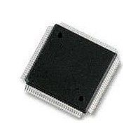
IC MCU 256K FLASH 25MHZ 112-LQFP
Manufacturer
Freescale Semiconductor
Series
HCS12r
Datasheet
1.S912XDG128F2MAL.pdf
(1348 pages)
Specifications of MC9S12DT256MPVE
Core Processor
HCS12
Core Size
16-Bit
Speed
25MHz
Connectivity
CAN, I²C, SCI, SPI
Peripherals
PWM, WDT
Number Of I /o
91
Program Memory Size
256KB (256K x 8)
Program Memory Type
FLASH
Eeprom Size
4K x 8
Ram Size
12K x 8
Voltage - Supply (vcc/vdd)
2.35 V ~ 5.25 V
Data Converters
A/D 8x10b
Oscillator Type
Internal
Operating Temperature
-40°C ~ 125°C
Package / Case
112-LQFP
Processor Series
S12D
Core
HCS12
Data Bus Width
16 bit
Data Ram Size
12 KB
Interface Type
CAN/I2C/SCI/SPI
Maximum Clock Frequency
25 MHz
Number Of Programmable I/os
91
Number Of Timers
1
Operating Supply Voltage
5 V to 2.5 V
Maximum Operating Temperature
+ 125 C
Mounting Style
SMD/SMT
3rd Party Development Tools
EWHCS12
Development Tools By Supplier
M68KIT912DP256
Minimum Operating Temperature
- 40 C
On-chip Adc
2 (8-ch x 10-bit)
No. Of I/o's
91
Eeprom Memory Size
4KB
Ram Memory Size
12KB
Cpu Speed
25MHz
No. Of Timers
1
No. Of Pwm Channels
8
Digital Ic Case Style
LQFP
Rohs Compliant
Yes
Lead Free Status / RoHS Status
Lead free / RoHS Compliant
Available stocks
Company
Part Number
Manufacturer
Quantity
Price

Company:
Part Number:
MC9S12DT256MPVE
Manufacturer:
Freescale Semiconductor
Quantity:
10 000


See
To calculate the output duty cycle (high time as a% of period) for a particular channel:
For boundary case programming values, please refer to
Read: Anytime
Write: Anytime
8.3.2.15
The PWMSDN register provides for the shutdown functionality of the PWM module in the emergency
cases. For proper operation, channel 7 must be driven to the active level for a minimum of two bus clocks.
Read: Anytime
Write: Anytime
Freescale Semiconductor
Reset
Reset
•
•
Section 8.4.2.3, “PWM Period and Duty”
W
W
R
R
Polarity = 0 (PPOL x =0)
Polarity = 1 (PPOLx = 1)
Duty Cycle = [(PWMPERx-PWMDTYx)/PWMPERx] * 100%
Duty Cycle = [PWMDTYx / PWMPERx] * 100%
PWMIF
Bit 7
PWM Shutdown Register (PWMSDN)
1
0
7
7
Reads of this register return the most recent value written. Reads do not
necessarily return the value of the currently active duty due to the double
buffering scheme.
Depending on the polarity bit, the duty registers will contain the count of
either the high time or the low time. If the polarity bit is one, the output starts
high and then goes low when the duty count is reached, so the duty registers
contain a count of the high time. If the polarity bit is zero, the output starts
low and then goes high when the duty count is reached, so the duty registers
contain a count of the low time.
= Unimplemented or Reserved
PWMIE
Figure 8-16. PWM Channel Duty Registers (PWMDTYx)
1
0
6
6
6
Figure 8-17. PWM Shutdown Register (PWMSDN)
PWMRSTRT
MC9S12XDP512 Data Sheet, Rev. 2.21
1
0
0
5
5
5
for more information.
PWMLVL
NOTE
NOTE
1
0
4
4
4
Section 8.4.2.8, “PWM Boundary
1
0
0
3
3
3
Chapter 8 Pulse-Width Modulator (S12PWM8B8CV1)
PWM7IN
1
0
2
2
2
PWM7INL
1
0
1
1
1
Cases”.
PWM7ENA
Bit 0
1
0
0
0
379
Related parts for MC9S12DT256MPVE
Image
Part Number
Description
Manufacturer
Datasheet
Request
R

Part Number:
Description:
Manufacturer:
Freescale Semiconductor, Inc
Datasheet:
Part Number:
Description:
Manufacturer:
Freescale Semiconductor, Inc
Datasheet:
Part Number:
Description:
Manufacturer:
Freescale Semiconductor, Inc
Datasheet:
Part Number:
Description:
Manufacturer:
Freescale Semiconductor, Inc
Datasheet:
Part Number:
Description:
Manufacturer:
Freescale Semiconductor, Inc
Datasheet:
Part Number:
Description:
Manufacturer:
Freescale Semiconductor, Inc
Datasheet:
Part Number:
Description:
Manufacturer:
Freescale Semiconductor, Inc
Datasheet:
Part Number:
Description:
Manufacturer:
Freescale Semiconductor, Inc
Datasheet:
Part Number:
Description:
Manufacturer:
Freescale Semiconductor, Inc
Datasheet:
Part Number:
Description:
Manufacturer:
Freescale Semiconductor, Inc
Datasheet:
Part Number:
Description:
Manufacturer:
Freescale Semiconductor, Inc
Datasheet:
Part Number:
Description:
Manufacturer:
Freescale Semiconductor, Inc
Datasheet:
Part Number:
Description:
Manufacturer:
Freescale Semiconductor, Inc
Datasheet:
Part Number:
Description:
Manufacturer:
Freescale Semiconductor, Inc
Datasheet:
Part Number:
Description:
Manufacturer:
Freescale Semiconductor, Inc
Datasheet: