MC9S12DT256MPVE Freescale Semiconductor, MC9S12DT256MPVE Datasheet - Page 619
MC9S12DT256MPVE
Manufacturer Part Number
MC9S12DT256MPVE
Description
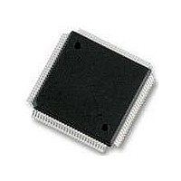
IC MCU 256K FLASH 25MHZ 112-LQFP
Manufacturer
Freescale Semiconductor
Series
HCS12r
Datasheet
1.S912XDG128F2MAL.pdf
(1348 pages)
Specifications of MC9S12DT256MPVE
Core Processor
HCS12
Core Size
16-Bit
Speed
25MHz
Connectivity
CAN, I²C, SCI, SPI
Peripherals
PWM, WDT
Number Of I /o
91
Program Memory Size
256KB (256K x 8)
Program Memory Type
FLASH
Eeprom Size
4K x 8
Ram Size
12K x 8
Voltage - Supply (vcc/vdd)
2.35 V ~ 5.25 V
Data Converters
A/D 8x10b
Oscillator Type
Internal
Operating Temperature
-40°C ~ 125°C
Package / Case
112-LQFP
Processor Series
S12D
Core
HCS12
Data Bus Width
16 bit
Data Ram Size
12 KB
Interface Type
CAN/I2C/SCI/SPI
Maximum Clock Frequency
25 MHz
Number Of Programmable I/os
91
Number Of Timers
1
Operating Supply Voltage
5 V to 2.5 V
Maximum Operating Temperature
+ 125 C
Mounting Style
SMD/SMT
3rd Party Development Tools
EWHCS12
Development Tools By Supplier
M68KIT912DP256
Minimum Operating Temperature
- 40 C
On-chip Adc
2 (8-ch x 10-bit)
No. Of I/o's
91
Eeprom Memory Size
4KB
Ram Memory Size
12KB
Cpu Speed
25MHz
No. Of Timers
1
No. Of Pwm Channels
8
Digital Ic Case Style
LQFP
Rohs Compliant
Yes
Lead Free Status / RoHS Status
Lead free / RoHS Compliant
Available stocks
Company
Part Number
Manufacturer
Quantity
Price

Company:
Part Number:
MC9S12DT256MPVE
Manufacturer:
Freescale Semiconductor
Quantity:
10 000


17.3.2.2
Read: Anytime. In emulation modes read operations will return the data read from the external bus. In all
other modes the data are read from this register.
Write: Only if a transition is allowed (see
directed to the external bus.
The MODE bits of the MODE register are used to establish the MCU operating mode.
Freescale Semiconductor
Address: 0x000B PRR
1. External signal (see
Reset
MODC,
MODB,
MODA
Field
7–5
W
R
MODC
MODC
Mode Select Bits — These bits control the current operating mode during RESET high (inactive). The external
mode pins MODC, MODB, and MODA determine the operating mode during RESET low (active). The state of
the pins is latched into the respective register bits after the RESET signal goes inactive (see
Write restrictions exist to disallow transitions between certain modes.
changes. Attempting non authorized transitions will not change the MODE bits, but it will block further writes to
these register bits except in special modes.
Both transitions from normal single-chip mode to normal expanded mode and from emulation single-chip to
emulation expanded mode are only executed by writing a value of 0b101 (write once). Writing any other value
will not change the MODE bits, but will block further writes to these register bits.
Changes of operating modes are not allowed when the device is secured, but it will block further writes to these
register bits except in special modes.
In emulation modes reading this address returns data from the external bus which has to be driven by the
emulator. It is therefore responsibility of the emulator hardware to provide the expected value (i.e. a value
corresponding to normal single chip mode while the device is in emulation single-chip mode or a value
corresponding to normal expanded mode while the device is in emulation expanded mode).
Mode Register (MODE)
7
XGATE write access to this register during an CPU access which makes use
of this register could lead to unexpected results.
1
Table
= Unimplemented or Reserved
MODB
MODB
1-2).
6
1
Table 17-6. MODE Field Descriptions
Figure 17-4. Mode Register (MODE)
MODA
MC9S12XDP512 Data Sheet, Rev. 2.21
MODA
5
1
Figure
CAUTION
1-5). In emulation modes write operations will be also
0
0
4
Description
0
0
3
Chapter 17 Memory Mapping Control (S12XMMCV2)
Figure 1-5
0
0
2
illustrates all allowed mode
0
0
1
Figure
1-5).
0
0
0
619
Related parts for MC9S12DT256MPVE
Image
Part Number
Description
Manufacturer
Datasheet
Request
R

Part Number:
Description:
Manufacturer:
Freescale Semiconductor, Inc
Datasheet:
Part Number:
Description:
Manufacturer:
Freescale Semiconductor, Inc
Datasheet:
Part Number:
Description:
Manufacturer:
Freescale Semiconductor, Inc
Datasheet:
Part Number:
Description:
Manufacturer:
Freescale Semiconductor, Inc
Datasheet:
Part Number:
Description:
Manufacturer:
Freescale Semiconductor, Inc
Datasheet:
Part Number:
Description:
Manufacturer:
Freescale Semiconductor, Inc
Datasheet:
Part Number:
Description:
Manufacturer:
Freescale Semiconductor, Inc
Datasheet:
Part Number:
Description:
Manufacturer:
Freescale Semiconductor, Inc
Datasheet:
Part Number:
Description:
Manufacturer:
Freescale Semiconductor, Inc
Datasheet:
Part Number:
Description:
Manufacturer:
Freescale Semiconductor, Inc
Datasheet:
Part Number:
Description:
Manufacturer:
Freescale Semiconductor, Inc
Datasheet:
Part Number:
Description:
Manufacturer:
Freescale Semiconductor, Inc
Datasheet:
Part Number:
Description:
Manufacturer:
Freescale Semiconductor, Inc
Datasheet:
Part Number:
Description:
Manufacturer:
Freescale Semiconductor, Inc
Datasheet:
Part Number:
Description:
Manufacturer:
Freescale Semiconductor, Inc
Datasheet: