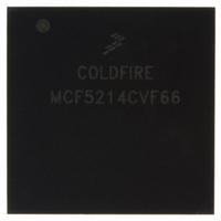
MCF5214CVF66 Freescale Semiconductor, MCF5214CVF66 Datasheet - Page 158

MCF5214CVF66
Manufacturer Part Number
MCF5214CVF66
Description
IC MPU 32BIT COLDF 256-MAPBGA
Manufacturer
Freescale Semiconductor
Series
MCF521xr
Datasheet
1.MCF5216CVM66J.pdf
(766 pages)
Specifications of MCF5214CVF66
Core Processor
Coldfire V2
Core Size
32-Bit
Speed
66MHz
Connectivity
CAN, EBI/EMI, I²C, SPI, UART/USART
Peripherals
DMA, LVD, POR, PWM, WDT
Number Of I /o
142
Program Memory Size
256KB (256K x 8)
Program Memory Type
FLASH
Ram Size
64K x 8
Voltage - Supply (vcc/vdd)
2.7 V ~ 3.6 V
Data Converters
A/D 8x12b
Oscillator Type
Internal
Operating Temperature
-40°C ~ 85°C
Package / Case
256-MAPBGA
Package
256MA-BGA
Device Core
ColdFire
Family Name
MCF521x
Maximum Speed
66 MHz
Operating Supply Voltage
3.3 V
Data Bus Width
32 Bit
Number Of Programmable I/os
142
Interface Type
QSPI/UART/I2C/CAN
On-chip Adc
8-chx10-bit
Number Of Timers
8
Lead Free Status / RoHS Status
Contains lead / RoHS non-compliant
Eeprom Size
-
Available stocks
Company
Part Number
Manufacturer
Quantity
Price
Company:
Part Number:
MCF5214CVF66
Manufacturer:
Freescale Semiconductor
Quantity:
10 000
Company:
Part Number:
MCF5214CVF66J
Manufacturer:
Freescale Semiconductor
Quantity:
10 000
- Current page: 158 of 766
- Download datasheet (9Mb)
System Control Module (SCM)
When the core watchdog timer times out and CWCR[CWRI] is programmed for a software reset, an
internal reset is asserted and CRSR[CWDR] is set. To prevent the core watchdog timer from interrupting
or resetting, the CWSR must be serviced by performing the following sequence:
Both writes must occur in order before the time-out, but any number of instructions can be executed
between the two writes. This order allows interrupts and exceptions to occur, if necessary, between the two
writes. Caution should be exercised when changing CWCR values after the software watchdog timer has
been enabled with the setting of CWCR[CWE], because it is difficult to determine the state of the core
watchdog timer while it is running. The countdown value is constantly compared with the time-out period
specified by CWCR[CWT]. The following steps must be taken to change CWT:
The CWCR controls the software watchdog timer, time-out periods, and software watchdog timer transfer
acknowledge. The register can be read at any time, but can be written only if the CWT is not pending. At
system reset, the software watchdog timer is disabled.
8-6
1. Write 0x55 to CWSR.
2. Write 0xAA to the CWSR.
1. Disable the core watchdog timer by clearing CWCR[CWE].
2. Reset the counter by writing 0x55 and then 0xAA to CWSR.
3. Update CWCR[CWT].
4. Re-enable the core watchdog timer by setting CWCR[CWE]. This step can be performed in step
Bits
7
6
3.
Name
CWRI
CWE
Address
Reset
Field
R/W
Core watchdog enable.
0 SWT disabled.
1 SWT enabled.
Core watchdog reset/interrupt select.
0 If a time-out occurs, the CWT generates an interrupt to the processor core. The interrupt level for
1 Reserved; do not use.
the CWT is programmed in the interrupt control register 8 (ICR8) of INTC0.
MCF5282 and MCF5216 ColdFire Microcontroller User’s Manual, Rev. 3
CWE
Figure 8-4. Core Watchdog Control Register (CWCR)
7
CWRI
6
Table 8-5. CWCR Field Description
5
CWT[2:0]
IPSBAR + 0x011
0000_0000
R/W
Description
3
CWTA
2
CWTAVAL
1
CWTIC
Freescale Semiconductor
0
Related parts for MCF5214CVF66
Image
Part Number
Description
Manufacturer
Datasheet
Request
R
Part Number:
Description:
Manufacturer:
Freescale Semiconductor, Inc
Datasheet:
Part Number:
Description:
Manufacturer:
Freescale Semiconductor, Inc
Datasheet:
Part Number:
Description:
Manufacturer:
Freescale Semiconductor, Inc
Datasheet:
Part Number:
Description:
Manufacturer:
Freescale Semiconductor, Inc
Datasheet:
Part Number:
Description:
Manufacturer:
Freescale Semiconductor, Inc
Datasheet:
Part Number:
Description:
Manufacturer:
Freescale Semiconductor, Inc
Datasheet:
Part Number:
Description:
Manufacturer:
Freescale Semiconductor, Inc
Datasheet:
Part Number:
Description:
Manufacturer:
Freescale Semiconductor, Inc
Datasheet:
Part Number:
Description:
Manufacturer:
Freescale Semiconductor, Inc
Datasheet:
Part Number:
Description:
Manufacturer:
Freescale Semiconductor, Inc
Datasheet:
Part Number:
Description:
Manufacturer:
Freescale Semiconductor, Inc
Datasheet:
Part Number:
Description:
Manufacturer:
Freescale Semiconductor, Inc
Datasheet:
Part Number:
Description:
Manufacturer:
Freescale Semiconductor, Inc
Datasheet:
Part Number:
Description:
Manufacturer:
Freescale Semiconductor, Inc
Datasheet:
Part Number:
Description:
Manufacturer:
Freescale Semiconductor, Inc
Datasheet:


