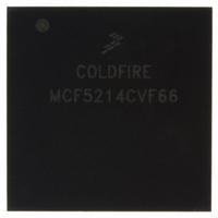
MCF5214CVF66 Freescale Semiconductor, MCF5214CVF66 Datasheet - Page 688

MCF5214CVF66
Manufacturer Part Number
MCF5214CVF66
Description
IC MPU 32BIT COLDF 256-MAPBGA
Manufacturer
Freescale Semiconductor
Series
MCF521xr
Datasheet
1.MCF5216CVM66J.pdf
(766 pages)
Specifications of MCF5214CVF66
Core Processor
Coldfire V2
Core Size
32-Bit
Speed
66MHz
Connectivity
CAN, EBI/EMI, I²C, SPI, UART/USART
Peripherals
DMA, LVD, POR, PWM, WDT
Number Of I /o
142
Program Memory Size
256KB (256K x 8)
Program Memory Type
FLASH
Ram Size
64K x 8
Voltage - Supply (vcc/vdd)
2.7 V ~ 3.6 V
Data Converters
A/D 8x12b
Oscillator Type
Internal
Operating Temperature
-40°C ~ 85°C
Package / Case
256-MAPBGA
Package
256MA-BGA
Device Core
ColdFire
Family Name
MCF521x
Maximum Speed
66 MHz
Operating Supply Voltage
3.3 V
Data Bus Width
32 Bit
Number Of Programmable I/os
142
Interface Type
QSPI/UART/I2C/CAN
On-chip Adc
8-chx10-bit
Number Of Timers
8
Lead Free Status / RoHS Status
Contains lead / RoHS non-compliant
Eeprom Size
-
Available stocks
Company
Part Number
Manufacturer
Quantity
Price
Company:
Part Number:
MCF5214CVF66
Manufacturer:
Freescale Semiconductor
Quantity:
10 000
Company:
Part Number:
MCF5214CVF66J
Manufacturer:
Freescale Semiconductor
Quantity:
10 000
- Current page: 688 of 766
- Download datasheet (9Mb)
1
2
System clocks disabled (LPCR[STPMD] = 00)
System clocks and CLKOUT disabled (LPCR[STPMD] =
01)
System clocks, CLKOUT, and PLL disabled
(LPCR[STPMD] = 10)
System clocks, CLKOUT, PLL, and OSC disabled
(LPCR[STPMD] = 11)
Single chip mode current measured with all pins in general purpose input mode except for the UART0 and FEC pins that are enabled
for their module functionality.
Maximum values can vary depending on the system’s state and signal loading.
Electrical Characteristics
33.4
Figure 33-1
chip mode as measured on an M5282EVB.
For master mode the RUN mode current was measured executing a continuous loop that performs no
operation while running from the on-chip SRAM.
For WAIT/DOZE mode measurements the peripherals on the device are in their default power savings
mode, so the WAIT and DOZE power consumption are the same. Some modules can be programmed to
shutdown in WAIT and/or DOZE modes. Refer to module chapters for more information.
All single chip mode measurements were taken with all pins in general purpose input mode except for the
UART0 and FEC pins that are enabled for their module functionality; however, neither module is being
accessed at the time of the current measurement. Single chip RUN mode current was measured executing
a continuous loop that performs no operation while running from the on-chip Flash.
33-4
Power Consumption Specifications
1
2
3
Load Capacitance
Supply Voltage (includes core modules and pads)
RAM Memory Standby Supply Voltage
(not applicable to MCF5280)
Flash Memory Supply Voltage
Normal Operation: V
Standby Mode: V
Refer to
This parameter is characterized before qualification rather than 100% tested.
Refer to the chip configuration section for more information. Drivers for the SDRAM pins are at 25pF
drive strength.Drivers for the QADC pins are at 50pF drive strength.
shows typical WAIT/DOZE and RUN mode power consumption for both master and single
(50% Partial Drive)
(100% Full Drive)
Characteristic
Table 33-8
Table 33-4. STOP Mode Current Consumption Specifications
MCF5282 and MCF5216 ColdFire Microcontroller User’s Manual, Rev. 3
3
DD
Table 33-3. DC Electrical Specifications
Characteristic
< V
through
DD
> V
STBY
STBY
Table 33-12
- 0.3 V
(V
SS
- 0.3 V
= V
SSPLL
for additional PLL, QADC, and Flash specifications.
Symbol
= V
I
I
I
I
DD
DD
DD
DD
SSF
= V
SSA
Master Mode
Typical–
= 0 V
Symbol
V
V
400
V
7.3
4.5
25
STBY
C
DDF
DD
L
DC
1
(continued)
)
Min
2.7
0.0
1.8
2.7
Single Chip
Typical–
Mode
750
7.9
5.6
4.7
1
Max
3.6
3.6
3.6
3.6
25
50
Freescale Semiconductor
Unit
pF
V
V
V
Max
1000
—
—
—
2
Unit
mA
mA
mA
μA
Related parts for MCF5214CVF66
Image
Part Number
Description
Manufacturer
Datasheet
Request
R
Part Number:
Description:
Manufacturer:
Freescale Semiconductor, Inc
Datasheet:
Part Number:
Description:
Manufacturer:
Freescale Semiconductor, Inc
Datasheet:
Part Number:
Description:
Manufacturer:
Freescale Semiconductor, Inc
Datasheet:
Part Number:
Description:
Manufacturer:
Freescale Semiconductor, Inc
Datasheet:
Part Number:
Description:
Manufacturer:
Freescale Semiconductor, Inc
Datasheet:
Part Number:
Description:
Manufacturer:
Freescale Semiconductor, Inc
Datasheet:
Part Number:
Description:
Manufacturer:
Freescale Semiconductor, Inc
Datasheet:
Part Number:
Description:
Manufacturer:
Freescale Semiconductor, Inc
Datasheet:
Part Number:
Description:
Manufacturer:
Freescale Semiconductor, Inc
Datasheet:
Part Number:
Description:
Manufacturer:
Freescale Semiconductor, Inc
Datasheet:
Part Number:
Description:
Manufacturer:
Freescale Semiconductor, Inc
Datasheet:
Part Number:
Description:
Manufacturer:
Freescale Semiconductor, Inc
Datasheet:
Part Number:
Description:
Manufacturer:
Freescale Semiconductor, Inc
Datasheet:
Part Number:
Description:
Manufacturer:
Freescale Semiconductor, Inc
Datasheet:
Part Number:
Description:
Manufacturer:
Freescale Semiconductor, Inc
Datasheet:


