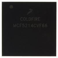
MCF5214CVF66 Freescale Semiconductor, MCF5214CVF66 Datasheet - Page 409

MCF5214CVF66
Manufacturer Part Number
MCF5214CVF66
Description
IC MPU 32BIT COLDF 256-MAPBGA
Manufacturer
Freescale Semiconductor
Series
MCF521xr
Datasheet
1.MCF5216CVM66J.pdf
(766 pages)
Specifications of MCF5214CVF66
Core Processor
Coldfire V2
Core Size
32-Bit
Speed
66MHz
Connectivity
CAN, EBI/EMI, I²C, SPI, UART/USART
Peripherals
DMA, LVD, POR, PWM, WDT
Number Of I /o
142
Program Memory Size
256KB (256K x 8)
Program Memory Type
FLASH
Ram Size
64K x 8
Voltage - Supply (vcc/vdd)
2.7 V ~ 3.6 V
Data Converters
A/D 8x12b
Oscillator Type
Internal
Operating Temperature
-40°C ~ 85°C
Package / Case
256-MAPBGA
Package
256MA-BGA
Device Core
ColdFire
Family Name
MCF521x
Maximum Speed
66 MHz
Operating Supply Voltage
3.3 V
Data Bus Width
32 Bit
Number Of Programmable I/os
142
Interface Type
QSPI/UART/I2C/CAN
On-chip Adc
8-chx10-bit
Number Of Timers
8
Lead Free Status / RoHS Status
Contains lead / RoHS non-compliant
Eeprom Size
-
Available stocks
Company
Part Number
Manufacturer
Quantity
Price
Company:
Part Number:
MCF5214CVF66
Manufacturer:
Freescale Semiconductor
Quantity:
10 000
Company:
Part Number:
MCF5214CVF66J
Manufacturer:
Freescale Semiconductor
Quantity:
10 000
- Current page: 409 of 766
- Download datasheet (9Mb)
Figure 22-3
22.3.2
The QDLYR is used to initiate master mode transfers and to set various delay parameters.
Freescale Semiconductor
IPSBAR
Field
14–8
QCD
Offset:
SPE
DTL
7–0
QSPI_DOUT
Reset
15
QSPI_CLK
QSPI_DIN
QSPI_CS
W
R
0x00_0344 (QDLYR)
QSPI enable. When set, the QSPI initiates transfers in master mode by executing commands in the command RAM.
The QSPI clears this bit automatically when a transfer completes. The user can also clear this bit to abort transfer
unless QIR[ABRTL] is set. The recommended method for aborting transfers is to set QWR[HALT].
QSPI_CLK delay. When the DSCK bit in the command RAM is set this field determines the length of the delay from
assertion of the chip selects to valid QSPI_CLK transition. See
setting this bit field.
Delay after transfer. When the DT bit in the command RAM is set this field determines the length of delay after the
serial transfer.
SPE
15
0
QSPI Delay Register (QDLYR)
shows an example of a QSPI clocking and data transfer.
14
0
QMR[CPOL] = 0
QMR[CPHA] = 1
QCR[CONT] = 0
msb
15
15
13
0
MCF5282 and MCF5216 ColdFire Microcontroller User’s Manual, Rev. 3
A
Figure 22-3. QSPI Clocking and Data Transfer Example
14
14
12
13
13
0
Figure 22-4. QSPI Delay Register (QDLYR)
Table 22-4. QDLYR Field Descriptions
QCD
12
12
11
0
11
11
10
1
10
10
9
9
0
9
Description
8
8
0
8
7
7
0
7
Section 22.4.3, “Transfer Delays”
6
6
Chip selects are active low
A = QDLYR[QCD]
B = QDLYR[DTL]
0
5
5
6
4
4
Queued Serial Peripheral Interface (QSPI)
0
5
3
3
0
4
DTL
2
2
0
3
1
1
Access: User read/write
0
0
for information on
1
2
B
0
1
22-5
0
0
Related parts for MCF5214CVF66
Image
Part Number
Description
Manufacturer
Datasheet
Request
R
Part Number:
Description:
Manufacturer:
Freescale Semiconductor, Inc
Datasheet:
Part Number:
Description:
Manufacturer:
Freescale Semiconductor, Inc
Datasheet:
Part Number:
Description:
Manufacturer:
Freescale Semiconductor, Inc
Datasheet:
Part Number:
Description:
Manufacturer:
Freescale Semiconductor, Inc
Datasheet:
Part Number:
Description:
Manufacturer:
Freescale Semiconductor, Inc
Datasheet:
Part Number:
Description:
Manufacturer:
Freescale Semiconductor, Inc
Datasheet:
Part Number:
Description:
Manufacturer:
Freescale Semiconductor, Inc
Datasheet:
Part Number:
Description:
Manufacturer:
Freescale Semiconductor, Inc
Datasheet:
Part Number:
Description:
Manufacturer:
Freescale Semiconductor, Inc
Datasheet:
Part Number:
Description:
Manufacturer:
Freescale Semiconductor, Inc
Datasheet:
Part Number:
Description:
Manufacturer:
Freescale Semiconductor, Inc
Datasheet:
Part Number:
Description:
Manufacturer:
Freescale Semiconductor, Inc
Datasheet:
Part Number:
Description:
Manufacturer:
Freescale Semiconductor, Inc
Datasheet:
Part Number:
Description:
Manufacturer:
Freescale Semiconductor, Inc
Datasheet:
Part Number:
Description:
Manufacturer:
Freescale Semiconductor, Inc
Datasheet:


