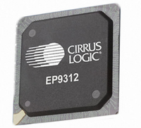
EP9312-CB Cirrus Logic Inc, EP9312-CB Datasheet - Page 605

EP9312-CB
Manufacturer Part Number
EP9312-CB
Description
System-on-Chip Processor
Manufacturer
Cirrus Logic Inc
Series
EP9r
Datasheets
1.EP9307-CRZ.pdf
(824 pages)
2.EP9312-IBZ.pdf
(4 pages)
3.EP9312-CB.pdf
(62 pages)
4.EP9312-CB.pdf
(17 pages)
Specifications of EP9312-CB
Peak Reflow Compatible (260 C)
No
A/d Converter
12 Bits
Leaded Process Compatible
No
No. Of I/o Pins
65
Package / Case
352-BGA
Core Processor
ARM9
Core Size
16/32-Bit
Speed
200MHz
Connectivity
EBI/EMI, EIDE, Ethernet, I²C, IrDA, Keypad/Touchscreen, SPI, UART/USART, USB
Peripherals
AC'97, DMA, I²:S, LCD, LED, MaverickKey, POR, PWM, WDT
Number Of I /o
16
Program Memory Type
ROMless
Ram Size
32K x 8
Voltage - Supply (vcc/vdd)
1.65 V ~ 3.6 V
Data Converters
A/D 8x12b
Oscillator Type
External
Operating Temperature
0°C ~ 70°C
Processor Series
EP93xx
Core
ARM920T
Data Bus Width
32 bit
3rd Party Development Tools
MDK-ARM, RL-ARM, ULINK2
Lead Free Status / RoHS Status
Contains lead / RoHS non-compliant
Eeprom Size
-
Program Memory Size
-
Lead Free Status / Rohs Status
No
Other names
598-1257
Available stocks
Company
Part Number
Manufacturer
Quantity
Price
Part Number:
EP9312-CB
Manufacturer:
CIRRUS
Quantity:
20 000
- EP9307-CRZ PDF datasheet
- EP9312-IBZ PDF datasheet #2
- EP9312-CB PDF datasheet #3
- EP9312-CB PDF datasheet #4
- Current page: 605 of 824
- Download datasheet (13Mb)
DS785UM1
17.4.1.2 Frame Format
MIR uses a flag (reserved bit pattern) to denote the beginning and end of a frame of
information and to synchronize frame transmission. A double flag is used to indicate the start
of a frame and a single flag the end. The flag contains eight bits, which start and end with a
zero and contain six sequential ones in the middle (01111110b). This sequence of six ones is
unique because all data between the start and stop flag is prohibited from having more than
five consecutive ones. Data that violates this rule is altered before transmission by
automatically inserting a zero after five consecutive ones are detected in the transmitted bit
stream. This technique is commonly referred to as “bit stuffing” and is transparent to the user.
The information field within a MIR frame is placed between the start and stop flags, consisting
of an 8 bit address, an optional 8 bit control field, a data field containing any multiple of 8 bits
and a 16 bit cyclic redundancy check (CRC-CCITT). Note that each byte within the address,
control and data fields is transmitted and received LSB first, ending with the byte’s MSB.
However, the CRC is transmitted and received MSB first. The MIR frame format is outlined
below in
Start Flag
0111 1110
8 Bits
Table
17-3.
Start Flag
0111 1110
8 Bits
Figure 17-1. RZ1/NRZ Bit Encoding Example
Address
8 Bits
Table 17-3. MIR Frame Format
Copyright 2007 Cirrus Logic
(optional)
Control
8 Bits
Any multiple
of 8 Bits
Data
CRC-CCITT
16 Bits
Stop Flag
0111 1110
8 Bits
EP93xx User’s Guide
IrDA
17-9
17
Related parts for EP9312-CB
Image
Part Number
Description
Manufacturer
Datasheet
Request
R

Part Number:
Description:
IC ARM920T MCU 200MHZ 352-PBGA
Manufacturer:
Cirrus Logic Inc
Datasheet:

Part Number:
Description:
IC ARM9 SOC UNIVERSAL 352PBGA
Manufacturer:
Cirrus Logic Inc
Datasheet:

Part Number:
Description:
IC ARM920T MCU 200MHZ 352-PBGA
Manufacturer:
Cirrus Logic Inc
Datasheet:

Part Number:
Description:
IC Universal Platform ARM9 SOC Prcessor
Manufacturer:
Cirrus Logic Inc
Datasheet:

Part Number:
Description:
IC Universal Platform ARM9 SOC Prcessor
Manufacturer:
Cirrus Logic Inc
Datasheet:

Part Number:
Description:
Development Kit
Manufacturer:
Cirrus Logic Inc
Datasheet:

Part Number:
Description:
Development Kit
Manufacturer:
Cirrus Logic Inc
Datasheet:

Part Number:
Description:
High-efficiency PFC + Fluorescent Lamp Driver Reference Design
Manufacturer:
Cirrus Logic Inc
Datasheet:

Part Number:
Description:
Development Kit
Manufacturer:
Cirrus Logic Inc
Datasheet:

Part Number:
Description:
Development Kit
Manufacturer:
Cirrus Logic Inc
Datasheet:

Part Number:
Description:
Development Kit
Manufacturer:
Cirrus Logic Inc
Datasheet:

Part Number:
Description:
Development Kit
Manufacturer:
Cirrus Logic Inc
Datasheet:

Part Number:
Description:
Ref Bd For Speakerbar MSA & DSP Products
Manufacturer:
Cirrus Logic Inc


