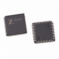
Z85C3008VSG Zilog, Z85C3008VSG Datasheet - Page 192

Z85C3008VSG
Manufacturer Part Number
Z85C3008VSG
Description
IC 8MHZ Z8500 CMOS SCC 44-PLCC
Manufacturer
Zilog
Series
SCCr
Specifications of Z85C3008VSG
Processor Type
Z80
Features
Error Detection and Multiprotocol Support
Speed
8MHz
Voltage
5V
Mounting Type
Surface Mount
Package / Case
44-LCC (J-Lead)
Maximum Operating Temperature
+ 70 C
Minimum Operating Temperature
0 C
Mounting Style
SMD/SMT
Cpu Speed
8MHz
Digital Ic Case Style
LCC
No. Of Pins
44
Supply Voltage Range
5V
Operating Temperature Range
0°C To +70°C
Svhc
No SVHC (18-Jun-2010)
Base Number
85
Rohs Compliant
Yes
Clock Frequency
8MHz
Lead Free Status / RoHS Status
Lead free / RoHS Compliant
Other names
269-3932
Z85C3008VSG
Z85C3008VSG
Available stocks
Company
Part Number
Manufacturer
Quantity
Price
Company:
Part Number:
Z85C3008VSG
Manufacturer:
Zilog
Quantity:
800
Company:
Part Number:
Z85C3008VSG
Manufacturer:
MAX
Quantity:
74
- Current page: 192 of 317
- Download datasheet (4Mb)
UM010901-0601
First, this program (Table 14) initializes the SCC by:
Then, it initializes 4K bytes of memory with a repeating
pattern beginning with 00h and increases by one to FFh
(uses this as Tx buffer area). Also, it begins another 4K
bytes of memory as a Rx buffer with all zeros. After
starting, DMA initialization follows:
DMAC0: For Rx data transfer: I/O to Mem, Source
address- fixed, Destination address-increasing. Edge
sense mode: Interrupt on end of transfer.
CONCLUSION
This Application Note describes only one example of
implementation, but gives you an idea of how to design the
system using the Z180™ and SCC.
Async, X1 mode, 8-bit 1 stop, Non-parity.
Tx and Rx clock from BRG, and BRG set to
PCLK/4.Self Loopback
DMAC1: For Tx data transfer: Mem to I/O, Source
address-increasing, Destination address - fixed. Edge
sense mode: Interrupt on end of transfer.
Now, start sending with DMA.
On completion of the transfer, the Z180 DMAC1 generates
an interrupt. Then, wait for the interrupt from DMAC0
which shows an end of receive. Now, compare received
data with sent data. If the transfer was successful (source
data matched with destination), 00h is left in the
accumulator. If not successful, 0FFh is left in the
accumulator.
This program example specifies a way to initialize the SCC
and the Z180 DMA.
For further design assistance, a completed board together
with the Debug/Monitor program and the listed sample
program are available. If interested, please contact your
local Zilog sales office.
The Z180™ Interfaced with the SCC at MHZ
Application Note
6-57
7
Related parts for Z85C3008VSG
Image
Part Number
Description
Manufacturer
Datasheet
Request
R

Part Number:
Description:
Manufacturer:
Zilog, Inc.
Datasheet:

Part Number:
Description:
Cmos Scc Serial Communications Controller
Manufacturer:
ZiLOG Semiconductor
Datasheet:

Part Number:
Description:
Communication Controllers, ZILOG INTELLIGENT PERIPHERAL CONTROLLER (ZIP)
Manufacturer:
Zilog, Inc.
Datasheet:

Part Number:
Description:
KIT DEV FOR Z8 ENCORE 16K TO 64K
Manufacturer:
Zilog
Datasheet:

Part Number:
Description:
KIT DEV Z8 ENCORE XP 28-PIN
Manufacturer:
Zilog
Datasheet:

Part Number:
Description:
DEV KIT FOR Z8 ENCORE 8K/4K
Manufacturer:
Zilog
Datasheet:

Part Number:
Description:
KIT DEV Z8 ENCORE XP 28-PIN
Manufacturer:
Zilog
Datasheet:

Part Number:
Description:
DEV KIT FOR Z8 ENCORE 4K TO 8K
Manufacturer:
Zilog
Datasheet:

Part Number:
Description:
CMOS Z8 microcontroller. ROM 16 Kbytes, RAM 256 bytes, speed 16 MHz, 32 lines I/O, 3.0V to 5.5V
Manufacturer:
Zilog, Inc.
Datasheet:

Part Number:
Description:
Low-cost microcontroller. 512 bytes ROM, 61 bytes RAM, 8 MHz
Manufacturer:
Zilog, Inc.
Datasheet:

Part Number:
Description:
Z8 4K OTP Microcontroller
Manufacturer:
Zilog, Inc.
Datasheet:

Part Number:
Description:
CMOS SUPER8 ROMLESS MCU
Manufacturer:
Zilog, Inc.
Datasheet:

Part Number:
Description:
SL1866 CMOSZ8 OTP Microcontroller
Manufacturer:
Zilog, Inc.
Datasheet:


