ST72T774J9B1 STMicroelectronics, ST72T774J9B1 Datasheet - Page 108
ST72T774J9B1
Manufacturer Part Number
ST72T774J9B1
Description
Manufacturer
STMicroelectronics
Datasheet
1.ST72T774J9B1.pdf
(144 pages)
Specifications of ST72T774J9B1
Cpu Family
ST7
Device Core Size
8b
Frequency (max)
24MHz
Interface Type
I2C/USB
Program Memory Type
EPROM
Program Memory Size
60KB
Total Internal Ram Size
1KB
# I/os (max)
31
Number Of Timers - General Purpose
1
Operating Supply Voltage (typ)
5V
Operating Supply Voltage (max)
5.5V
Operating Supply Voltage (min)
4V
On-chip Adc
1-chx8-bit
On-chip Dac
1-chx8-bit
Instruction Set Architecture
CISC
Operating Temp Range
0C to 70C
Operating Temperature Classification
Commercial
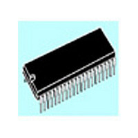
Mounting
Through Hole
Pin Count
42
Package Type
SPDIP
Lead Free Status / Rohs Status
Specific Sites Compliant
Available stocks
Company
Part Number
Manufacturer
Quantity
Price

Part Number:
ST72T774J9B1
Manufacturer:
ST
Quantity:
20 000


ST72774/ST727754/ST72734
DDC INTERFACE (Cont’d)
Slave Receiver
Following the address reception and after SR1
register has been read, the slave receives bytes
from the SDA line into the DR register via the
internal shift register. After each byte, the following
events occur in sequence:
– Acknowledge pulse is generated if the ACK bit is
– EVF and BTF bits are set.
– An interrupt is generated if the ITE bit is set.
Then the interface waits for a read of the SR1
register followed by a read of the DR register,
holding the SCL line low (see
sequencing EV2).
Slave Transmitter
Following the address reception and after SR1
register has been read, the slave sends bytes from
the DR register to the SDA line via the internal shift
register.
The slave waits for a read of the SR1 register
followed by a write in the DR register, holding the
SCL line low (see
EV3).
When the acknowledge pulse is received:
– EVF and BTF bits are set.
– An interrupt is generated if the ITE bit is set.
Closing slave communication
After the last data byte is transferred, a Stop
Condition is generated by the master. The
interface detects this condition and in this case:
– EVF and STOPF bits are set.
– An interrupt is generated if the ITE bit is set.
108/144
set.
Figure 67
Transfer sequencing
Figure 67
Transfer
Then the interface waits for a read of the SR2
register (see
Error Cases
– BERR: Detection of a Stop or a Start condition
– AF: Detection of a non-acknowledge bit. In this
Note:In both cases, SCL line is not held low; however,
How to release the SDA / SCL lines
Set and subsequently clear the STOP bit while
BTF is set. The SDA/SCL lines are released after
the transfer of the current byte.
Other Events
during a byte transfer. In this case, the EVF and
the BERR bits are set and an interrupt is gener-
ated if the ITE bit is set.
If it is a Stop then the interface discards the data,
releases the lines and waits for another Start
condition.
If it is a Start then the interface discards the data
and waits for the next slave address on the bus.
case, the EVF and AF bits are set and an inter-
rupt is generated if the ITE bit is set.
ADSL: Detection of a Start condition after an
acknowledge time-slot.
The state machine is reset and starts a new
process. The ADSL bit is set and an interrupt is
generated if the ITE bit is set. The SCL line is
stretched low.
STOPF: Detection of a Stop condition after an
acknowledge time-slot.
The state machine is reset. Then the STOPF
flag is set and an interrupt is generated if the ITE
bit is set.
SDA line can remain low due to possible «0» bits
transmitted last. It is then necessary to release both
lines by software.
Figure 67
Transfer sequencing EV4).
Related parts for ST72T774J9B1
Image
Part Number
Description
Manufacturer
Datasheet
Request
R

Part Number:
Description:
STMicroelectronics [RIPPLE-CARRY BINARY COUNTER/DIVIDERS]
Manufacturer:
STMicroelectronics
Datasheet:
Part Number:
Description:
STMicroelectronics [LIQUID-CRYSTAL DISPLAY DRIVERS]
Manufacturer:
STMicroelectronics
Datasheet:

Part Number:
Description:
BOARD EVAL FOR MEMS SENSORS
Manufacturer:
STMicroelectronics
Datasheet:
Part Number:
Description:
NPN TRANSISTOR POWER MODULE
Manufacturer:
STMicroelectronics
Datasheet:
Part Number:
Description:
TURBOSWITCH ULTRA-FAST HIGH VOLTAGE DIODE
Manufacturer:
STMicroelectronics
Datasheet:
Part Number:
Description:
Manufacturer:
STMicroelectronics
Datasheet:
Part Number:
Description:
DIODE / SCR MODULE
Manufacturer:
STMicroelectronics
Datasheet:
Part Number:
Description:
DIODE / SCR MODULE
Manufacturer:
STMicroelectronics
Datasheet:
Part Number:
Description:
Search -----> STE16N100
Manufacturer:
STMicroelectronics
Datasheet:
Part Number:
Description:
Search ---> STE53NA50
Manufacturer:
STMicroelectronics
Datasheet:
Part Number:
Description:
NPN Transistor Power Module
Manufacturer:
STMicroelectronics
Datasheet:
Part Number:
Description:
DIODE / SCR MODULE
Manufacturer:
STMicroelectronics
Datasheet: