ST72T774J9B1 STMicroelectronics, ST72T774J9B1 Datasheet - Page 47
ST72T774J9B1
Manufacturer Part Number
ST72T774J9B1
Description
Manufacturer
STMicroelectronics
Datasheet
1.ST72T774J9B1.pdf
(144 pages)
Specifications of ST72T774J9B1
Cpu Family
ST7
Device Core Size
8b
Frequency (max)
24MHz
Interface Type
I2C/USB
Program Memory Type
EPROM
Program Memory Size
60KB
Total Internal Ram Size
1KB
# I/os (max)
31
Number Of Timers - General Purpose
1
Operating Supply Voltage (typ)
5V
Operating Supply Voltage (max)
5.5V
Operating Supply Voltage (min)
4V
On-chip Adc
1-chx8-bit
On-chip Dac
1-chx8-bit
Instruction Set Architecture
CISC
Operating Temp Range
0C to 70C
Operating Temperature Classification
Commercial
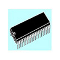
Mounting
Through Hole
Pin Count
42
Package Type
SPDIP
Lead Free Status / Rohs Status
Specific Sites Compliant
Available stocks
Company
Part Number
Manufacturer
Quantity
Price

Part Number:
ST72T774J9B1
Manufacturer:
ST
Quantity:
20 000


16-BIT TIMER (Cont’d)
4.3.3.4 Output Compare
In this section, the index, i , may be 1 or 2.
This function can be used to control an output
waveform or indicating when a period of time has
elapsed.
When a match is found between the Output
Compare register and the free running counter, the
output compare function:
Two 16-bit registers Output Compare Register 1
(OC1R) and Output Compare Register 2 (OC2R)
contain the value to be compared to the free
running counter each timer clock cycle.
These registers are readable and writable and are
not affected by the timer hardware. A reset event
changes the OC
Timing resolution is one count of the free running
counter: (
Procedure
To use the output compare function, select the
following in the CR2 register:
– Set the OC i E bit if an output is needed then the
– Select the timer clock (CC1-CC0) (see
And select the following in the CR1 register:
– Select the OLVL i bit to applied to the OCMP i pins
– Set the OCIE bit to generate an interrupt if it is
When match is found:
– OCF i bit is set.
– The OCMP i pin takes OLVL i bit value (OCMP i
OCMP i pin is dedicated to the output compare i
function.
Clock Control
after the match occurs.
needed.
pin latch is forced low during reset and stays low
until valid compares change it to a high level).
– Assigns pins with a programmable value if the
– Sets a flag in the status register
– Generates an interrupt if enabled
OC i R
OCIE bit is set
f
CPU/(CC1.CC0)
Bits).
i
R value to 8000h.
MS Byte
OC i HR
).
LS Byte
OC i LR
Table 15
– A timer interrupt is generated if the OCIE bit is
Clearing the output compare interrupt request is
done by:
3. Reading the SR register while the OCF i bit is
4. An access (read or write) to the OC i LR register.
Note: After a processor write cycle to the OC i HR register,
If the OC i E bit is not set, the OCMP i pin is a
general I/O port and the OLVL i bit will not appear
when match is found but an interrupt could be
generated if the OCIE bit is set.
The value in the 16-bit OC
bit should be changed after each successful
comparison in order to control an output waveform
or establish a new elapsed timeout.
The OC
timing application can be calculated using the
following formula:
Where:
f
CC1-CC0 = Timer clock prescaler
The following procedure is recommended to
prevent the OCF i bit from being set between the
time it is read and the write to the OC
– Write to the OC i HR register (further compares
– Read the SR register (first step of the clearance
– Write to the OC i LR register (enables the output
CPU
t
set in the CR2 register and the I bit is cleared in
the CC register (CC).
are inhibited).
of the OCF i bit, which may be already set).
compare function and clears the OCF i bit).
set.
the output compare function is inhibited until the
OC i LR register is also written.
i
R register value required for a specific
= Desired output compare period (in
= Internal clock frequency
seconds)
OC i R =
ST72774/ST727754/ST72734
i
(CC1.CC0)
R register and the OLV i
t
*
f
CPU
i
R register:
47/144
Related parts for ST72T774J9B1
Image
Part Number
Description
Manufacturer
Datasheet
Request
R

Part Number:
Description:
STMicroelectronics [RIPPLE-CARRY BINARY COUNTER/DIVIDERS]
Manufacturer:
STMicroelectronics
Datasheet:
Part Number:
Description:
STMicroelectronics [LIQUID-CRYSTAL DISPLAY DRIVERS]
Manufacturer:
STMicroelectronics
Datasheet:

Part Number:
Description:
BOARD EVAL FOR MEMS SENSORS
Manufacturer:
STMicroelectronics
Datasheet:
Part Number:
Description:
NPN TRANSISTOR POWER MODULE
Manufacturer:
STMicroelectronics
Datasheet:
Part Number:
Description:
TURBOSWITCH ULTRA-FAST HIGH VOLTAGE DIODE
Manufacturer:
STMicroelectronics
Datasheet:
Part Number:
Description:
Manufacturer:
STMicroelectronics
Datasheet:
Part Number:
Description:
DIODE / SCR MODULE
Manufacturer:
STMicroelectronics
Datasheet:
Part Number:
Description:
DIODE / SCR MODULE
Manufacturer:
STMicroelectronics
Datasheet:
Part Number:
Description:
Search -----> STE16N100
Manufacturer:
STMicroelectronics
Datasheet:
Part Number:
Description:
Search ---> STE53NA50
Manufacturer:
STMicroelectronics
Datasheet:
Part Number:
Description:
NPN Transistor Power Module
Manufacturer:
STMicroelectronics
Datasheet:
Part Number:
Description:
DIODE / SCR MODULE
Manufacturer:
STMicroelectronics
Datasheet: