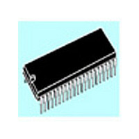
ST72T774J9B1 STMicroelectronics, ST72T774J9B1 Datasheet - Page 25

ST72T774J9B1
Manufacturer Part Number
ST72T774J9B1
Description
Manufacturer
STMicroelectronics
Datasheet
1.ST72T774J9B1.pdf
(144 pages)
Specifications of ST72T774J9B1
Cpu Family
ST7
Device Core Size
8b
Frequency (max)
24MHz
Interface Type
I2C/USB
Program Memory Type
EPROM
Program Memory Size
60KB
Total Internal Ram Size
1KB
# I/os (max)
31
Number Of Timers - General Purpose
1
Operating Supply Voltage (typ)
5V
Operating Supply Voltage (max)
5.5V
Operating Supply Voltage (min)
4V
On-chip Adc
1-chx8-bit
On-chip Dac
1-chx8-bit
Instruction Set Architecture
CISC
Operating Temp Range
0C to 70C
Operating Temperature Classification
Commercial
Mounting
Through Hole
Pin Count
42
Package Type
SPDIP
Lead Free Status / Rohs Status
Specific Sites Compliant
Available stocks
Company
Part Number
Manufacturer
Quantity
Price
Part Number:
ST72T774J9B1
Manufacturer:
ST
Quantity:
20 000
3.4 POWER SAVING MODES
3.4.1 WAIT Mode
This mode is a low power consumption mode. The
WFI instruction places the MCU in WAIT mode:
The internal clock remains active but all CPU
processing
peripherals are still running.
Note: In WAIT mode, DMA accesses (DDC, USB)
are possible.
During WAIT mode, the I bit in the condition code
register is cleared to enable all interrupts, which
causes the MCU to exit WAIT mode, causes the
corresponding interrupt vector to be fetched, the
interrupt routine to be executed and normal
processing to resume. A reset causes the program
counter to fetch the reset vector and processing
starts as for a normal reset.
Table 5
affected by the low power modes. For detailed
information on a particular device, please refer to
the corresponding part.
3.4.2 HALT Mode
The HALT mode is the MCU lowest power
consumption mode. Meanwhile, the HALT mode
also stops the oscillator stage completely which is
the most critical condition in CRT monitors.
For this reason, the HALT mode has been disabled
and its associated HALT instruction is now
considered as illegal and will generate a reset.
gives a list of the different sections
is
stopped;
however,
all
other
Figure 14. WAIT Flow Chart
Note: Before servicing an interrupt, the CC register is
pushed on the stack. The I-Bit is set during the inter-
rupt routine and cleared when the CC register is
popped.
N
INTERRUPT
Y
ST72774/ST727754/ST72734
OSCILLATOR
PERIPH. CLOCK
CPU CLOCK
I-BIT
N
OR SERVICE INTERRUPT
OSCILLATOR
PERIPH. CLOCK
CPU CLOCK
FETCH RESET VECTOR
I-BIT
WFI INSTRUCTION
4096 CPU CLOCK
CYCLES DELAY
IF RESET
RESET
Y
ON
ON
OFF
CLEARED
ON
ON
ON
SET
25/144


