ST72T774J9B1 STMicroelectronics, ST72T774J9B1 Datasheet - Page 93
ST72T774J9B1
Manufacturer Part Number
ST72T774J9B1
Description
Manufacturer
STMicroelectronics
Datasheet
1.ST72T774J9B1.pdf
(144 pages)
Specifications of ST72T774J9B1
Cpu Family
ST7
Device Core Size
8b
Frequency (max)
24MHz
Interface Type
I2C/USB
Program Memory Type
EPROM
Program Memory Size
60KB
Total Internal Ram Size
1KB
# I/os (max)
31
Number Of Timers - General Purpose
1
Operating Supply Voltage (typ)
5V
Operating Supply Voltage (max)
5.5V
Operating Supply Voltage (min)
4V
On-chip Adc
1-chx8-bit
On-chip Dac
1-chx8-bit
Instruction Set Architecture
CISC
Operating Temp Range
0C to 70C
Operating Temperature Classification
Commercial
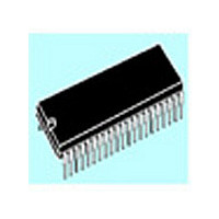
Mounting
Through Hole
Pin Count
42
Package Type
SPDIP
Lead Free Status / Rohs Status
Specific Sites Compliant
Available stocks
Company
Part Number
Manufacturer
Quantity
Price

Part Number:
ST72T774J9B1
Manufacturer:
ST
Quantity:
20 000


I²C SINGLE MASTER BUS INTERFACE (Cont’d)
I
Read Only
Reset Value: 0000 0000 (00h)
Bit 7:5 = Reserved. Forced to 0 by hardware.
Bit 4 = AF Acknowledge failure .
This bit is set by hardware when no acknowledge
is returned. An interrupt is generated if ITE=1. It is
cleared by software reading SR2 register or by
hardware when the interface is disabled (PE=0).
The SCL line is not held low while AF=1.
0: No acknowledge failure
1: Acknowledge failure
Bit 3:0 = Reserved. Forced to 0 by hardware.
I
Read / Write
Reset Value: 0000 0000 (00h)
Bit 7 = FM/SM Fast/Standard I
This bit is set and cleared by software. It is not
cleared when the interface is disabled (PE=0).
FM/SM
2
2
C STATUS REGISTER 2 (SR2)
C CLOCK CONTROL REGISTER (CCR)
7
0
7
CC6
0
CC5
0
CC4
AF
CC3
0
2
C mode.
CC2
0
CC1
0
CC0
0
0
0
0: Standard I
1: Fast I
Bit 6:0 = CC6-CC0 7-bit clock divider.
These bits select the speed of the bus (F
depending on the I
when the interface is disabled (PE=0).
– Standard mode (FM/SM=0): F
– Fast mode (FM/SM=1): F
Note: The programmed F
I
Read / Write
Reset Value: 0000 0000 (00h)
Bit 7:0 = D7-D0 8-bit Data Register.
These bits contains the byte to be received or
transmitted on the bus.
– Transmitter mode: Byte transmission start auto-
– Receiver mode: the first data byte is received au-
2
C DATA REGISTER (DR)
matically when the software writes in the DR reg-
ister.
tomatically in the DR register using the least sig-
nificant bit of the address.
Then, the next data bytes are received one by
one after reading the DR register.
D7
7
and SDA lines.
F
F
SCL
SCL
2
D6
C mode
= F
= F
2
C mode
D5
CPU
CPU
ST72774/ST727754/ST72734
2
/(2x([CC6..CC0]+2))
/(3x([CC6..CC0]+2))
C mode. They are not cleared
D4
SCL
assumes no load on SCL
D3
SCL
> 100kHz
SCL
D2
<= 100kHz
D1
93/144
SCL
D0
0
)
Related parts for ST72T774J9B1
Image
Part Number
Description
Manufacturer
Datasheet
Request
R

Part Number:
Description:
STMicroelectronics [RIPPLE-CARRY BINARY COUNTER/DIVIDERS]
Manufacturer:
STMicroelectronics
Datasheet:
Part Number:
Description:
STMicroelectronics [LIQUID-CRYSTAL DISPLAY DRIVERS]
Manufacturer:
STMicroelectronics
Datasheet:

Part Number:
Description:
BOARD EVAL FOR MEMS SENSORS
Manufacturer:
STMicroelectronics
Datasheet:
Part Number:
Description:
NPN TRANSISTOR POWER MODULE
Manufacturer:
STMicroelectronics
Datasheet:
Part Number:
Description:
TURBOSWITCH ULTRA-FAST HIGH VOLTAGE DIODE
Manufacturer:
STMicroelectronics
Datasheet:
Part Number:
Description:
Manufacturer:
STMicroelectronics
Datasheet:
Part Number:
Description:
DIODE / SCR MODULE
Manufacturer:
STMicroelectronics
Datasheet:
Part Number:
Description:
DIODE / SCR MODULE
Manufacturer:
STMicroelectronics
Datasheet:
Part Number:
Description:
Search -----> STE16N100
Manufacturer:
STMicroelectronics
Datasheet:
Part Number:
Description:
Search ---> STE53NA50
Manufacturer:
STMicroelectronics
Datasheet:
Part Number:
Description:
NPN Transistor Power Module
Manufacturer:
STMicroelectronics
Datasheet:
Part Number:
Description:
DIODE / SCR MODULE
Manufacturer:
STMicroelectronics
Datasheet: