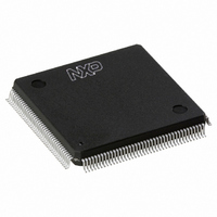
SAA7146AH/V4,557 NXP Semiconductors, SAA7146AH/V4,557 Datasheet - Page 116

SAA7146AH/V4,557
Manufacturer Part Number
SAA7146AH/V4,557
Description
IC VIDEO SPCI BRIDGE HP 160-QFP
Manufacturer
NXP Semiconductors
Type
Video Bridger
Datasheet
1.SAA7146AHV4557.pdf
(139 pages)
Specifications of SAA7146AH/V4,557
Package / Case
160-QFP
Applications
DTV
Mounting Type
Surface Mount
Maximum Operating Temperature
+ 70 C
Minimum Operating Temperature
0 C
Mounting Style
SMD/SMT
Lead Free Status / RoHS Status
Lead free / RoHS Compliant
Lead Free Status / RoHS Status
Lead free / RoHS Compliant, Lead free / RoHS Compliant
Other names
568-1318
935269343557
SAA7146AHBB
935269343557
SAA7146AHBB
Available stocks
Company
Part Number
Manufacturer
Quantity
Price
Company:
Part Number:
SAA7146AH/V4,557
Manufacturer:
NXP Semiconductors
Quantity:
10 000
- Current page: 116 of 139
- Download datasheet (576Kb)
Philips Semiconductors
7.17
7.17.1
The I
data exchange. Only two bus lines are required: a serial
clock line (SCL) and a serial data line (SDA). It’s a true
multi-master bus including collision detection and
arbitration to prevent data corruption if two or more
masters simultaneously initiate data transfers. Serial clock
synchronization allows devices with different bit rates to
communicate via the same serial bus. The block diagram
is shown in Fig.41.
7.17.2
The I
generation and bus control arbitration are controlled by
hardware. The status register (IICSTA) reflects the status
of the interface and the I
2004 Aug 25
handbook, full pagewidth
Multimedia bridge, high performance
Scaler and PCI circuit (SPCI)
2
2
C-bus is a simple 2-wire bus for efficient inter-IC
C-bus performs byte oriented data transfers. Clock
I
2
C-bus interface
G
F
UNCTIONAL DESCRIPTION
ENERAL DESCRIPTION
SDA
SCL
2
C-bus (see Table 110).
ARBITRATION AND SYNC LOGIC
Fig.41 Block diagram of I
BUS CLOCK GENERATOR
8-BIT SHIFT REGISTER
116
2
An interrupt after execution may be enabled optionally.
The bus clock generator supports clock rates from
5 to 400 kHz.
The I
control register (IICTRF) which is shown in Table 112.
A write to this register starts the transfer sequence where
up to 3 bytes are transferred: BYTE2, BYTE1 and BYTE0.
Any of these 3 bytes may be disabled or enabled for use
(as data byte or 7-bit address plus RW bit) in three I
protocol functions:
All bus operations are done via these three functions.
The functional usage of each single byte is defined by the
byte specific attribute information (see Table 113).
CONTROL
C-bus serial interface.
START: start/restart and address device
CONT: transfer data and continue
STOP: transfer data and stop.
2
STATUS REGISTER (IICSTA)
C-bus interface is programmed through the transfer
TRANSFER ATTRIBUTES
BYTE 0
BYTE 1
BYTE 2
MGG278
Product specification
SAA7146A
2
C-bus
Related parts for SAA7146AH/V4,557
Image
Part Number
Description
Manufacturer
Datasheet
Request
R
Part Number:
Description:
Manufacturer:
NXP Semiconductors
Datasheet:

Part Number:
Description:
Manufacturer:
NXP Semiconductors
Datasheet:
Part Number:
Description:
NXP Semiconductors designed the LPC2420/2460 microcontroller around a 16-bit/32-bitARM7TDMI-S CPU core with real-time debug interfaces that include both JTAG andembedded trace
Manufacturer:
NXP Semiconductors
Datasheet:

Part Number:
Description:
NXP Semiconductors designed the LPC2458 microcontroller around a 16-bit/32-bitARM7TDMI-S CPU core with real-time debug interfaces that include both JTAG andembedded trace
Manufacturer:
NXP Semiconductors
Datasheet:
Part Number:
Description:
NXP Semiconductors designed the LPC2468 microcontroller around a 16-bit/32-bitARM7TDMI-S CPU core with real-time debug interfaces that include both JTAG andembedded trace
Manufacturer:
NXP Semiconductors
Datasheet:
Part Number:
Description:
NXP Semiconductors designed the LPC2470 microcontroller, powered by theARM7TDMI-S core, to be a highly integrated microcontroller for a wide range ofapplications that require advanced communications and high quality graphic displays
Manufacturer:
NXP Semiconductors
Datasheet:
Part Number:
Description:
NXP Semiconductors designed the LPC2478 microcontroller, powered by theARM7TDMI-S core, to be a highly integrated microcontroller for a wide range ofapplications that require advanced communications and high quality graphic displays
Manufacturer:
NXP Semiconductors
Datasheet:
Part Number:
Description:
The Philips Semiconductors XA (eXtended Architecture) family of 16-bit single-chip microcontrollers is powerful enough to easily handle the requirements of high performance embedded applications, yet inexpensive enough to compete in the market for hi
Manufacturer:
NXP Semiconductors
Datasheet:
Part Number:
Description:
The XA-S3 device is a member of Philips Semiconductors? XA(eXtended Architecture) family of high performance 16-bitsingle-chip microcontrollers
Manufacturer:
NXP Semiconductors
Datasheet:

Part Number:
Description:
The NXP BlueStreak LH75401/LH75411 family consists of two low-cost 16/32-bit System-on-Chip (SoC) devices
Manufacturer:
NXP Semiconductors
Datasheet:

Part Number:
Description:
The NXP LPC3130/3131 combine an 180 MHz ARM926EJ-S CPU core, high-speed USB2
Manufacturer:
NXP Semiconductors
Datasheet:

Part Number:
Description:
The NXP LPC3141 combine a 270 MHz ARM926EJ-S CPU core, High-speed USB 2
Manufacturer:
NXP Semiconductors

Part Number:
Description:
The NXP LPC3143 combine a 270 MHz ARM926EJ-S CPU core, High-speed USB 2
Manufacturer:
NXP Semiconductors

Part Number:
Description:
The NXP LPC3152 combines an 180 MHz ARM926EJ-S CPU core, High-speed USB 2
Manufacturer:
NXP Semiconductors


