SAA7146AH/V4,557 NXP Semiconductors, SAA7146AH/V4,557 Datasheet - Page 95

SAA7146AH/V4,557
Manufacturer Part Number
SAA7146AH/V4,557
Description
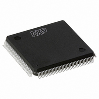
IC VIDEO SPCI BRIDGE HP 160-QFP
Manufacturer
NXP Semiconductors
Type
Video Bridger
Datasheet
1.SAA7146AHV4557.pdf
(139 pages)
Specifications of SAA7146AH/V4,557
Package / Case
160-QFP
Applications
DTV
Mounting Type
Surface Mount
Maximum Operating Temperature
+ 70 C
Minimum Operating Temperature
0 C
Mounting Style
SMD/SMT
Lead Free Status / RoHS Status
Lead free / RoHS Compliant
Lead Free Status / RoHS Status
Lead free / RoHS Compliant, Lead free / RoHS Compliant
Other names
568-1318
935269343557
SAA7146AHBB
935269343557
SAA7146AHBB
Available stocks
Company
Part Number
Manufacturer
Quantity
Price
Company:
Part Number:
SAA7146AH/V4,557
Manufacturer:
NXP Semiconductors
Quantity:
10 000
Philips Semiconductors
The two lists, pixel list and line list, are interlocked in the
64 Dword memory. The pixel list is located at the even
addresses, the line list at the odd addresses. This
organization reduces the number of Dwords to be loaded,
if there are less then 16 overlay windows. For example,
5 overlay windows need 20 Dwords for the coordinates
and 2 Dwords as EOF marker.
7.14.2.2
Overlay window coordinates are relative to the video
window and can range between 0, 0 and 2047. Relevant
coordinates are top/left, bottom + 1/right + 1 of the overlay
windows. If an overlay window has its bottom/right
coordinates at the bottom/right of the video window its
relevant coordinates bottom + 1/right + 1 would exceed
the coordinate range and therefore do not have to be
inserted into the lists.
Table 92 DEBI pin list
2004 Aug 25
AD15 to AD0
AS_ALE
UDS_WRN
LDS_RDN
RWN_SBHE
DTACK_RDY
GPIO3
Build lists: build sorted lists of lines and pixels containing
top/left, bottom + 1/right + 1 coordinates of every
overlay window, without having consecutive list entries
with the same coordinate. Every list will have an end of
list entry with all coordinate bits set to zero. This EOL
entry will follow the last entry. If there are 16 overlay
windows and no double coordinates the lists are full and
there is no last entry.
Insert display information: for every relevant coordinate
in both lists and for every overlay window, if the
coordinate in the line/pixel list is in between the
top/bottom or left/right coordinates of the overlay
window then set the display information bit to 1
(‘display’). Otherwise, set the display information bit to 0
(‘no_display’).
Multimedia bridge, high performance
Scaler and PCI circuit (SPCI)
PIN NAME
Driver algorithm
input/output
output
output
output
output
input
input/output
(used here as input only)
TYPE
multiplexed address and data lines
address strobe/address latch enable
upper data strobe/write not
lower data strobe/read not
read/write not/system byte HIGH enable
data acknowledge/ready (should be pulled HIGH if not used)
optional external interrupt input
95
7.15
7.15.1
The DEBI performs 16-bit parallel I/O in immediate (direct)
transfer mode and block transfer mode. The immediate
mode is used to transfer a byte, word or Dword to or from
the target device. The block transfer mode offers the
possibility to read or write up to 32 kbytes data blocks.
7.15.2
7.15.3
There are 21 DEBI pins. Most of the control signals
represent different functions with respect to the selected
interface mode (Intel/ISA or Motorola/68 kbytes).
8-bit and 16-bit slaves supported
External interrupt supported, DMA suspend/resume
function
Byte, word and Dword transfers supported
Slaves with or without handshake ability supported due
to programmable cycle time
Different endian types supported
PCI DMA master transfer in block mode
Optional address increment in block mode.
Data Expansion Bus Interface (DEBI)
G
F
DEBI
EATURES
ENERAL DESCRIPTION
PINS
DESCRIPTION
Product specification
SAA7146A


