DEMO9RS08KA2 Freescale Semiconductor, DEMO9RS08KA2 Datasheet - Page 21
DEMO9RS08KA2
Manufacturer Part Number
DEMO9RS08KA2
Description
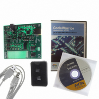
DEMO BOARD FOR 9RS08KA2
Manufacturer
Freescale Semiconductor
Series
RS08r
Type
MCUr
Datasheets
1.DEMO9RS08KA2.pdf
(136 pages)
2.DEMO9RS08KA2.pdf
(28 pages)
3.DEMO9RS08KA2.pdf
(2 pages)
4.DEMO9RS08KA2.pdf
(6 pages)
Specifications of DEMO9RS08KA2
Contents
Board, Cable, CD, Documentation, Sample ICs
Processor To Be Evaluated
RS08KA2
Data Bus Width
8 bit
Interface Type
USB
Silicon Manufacturer
Freescale
Core Architecture
RS08
Core Sub-architecture
RS08
Silicon Core Number
MC9RS08
Silicon Family Name
RS08KA
Rohs Compliant
Yes
For Use With/related Products
MC9RS08KA2
Lead Free Status / RoHS Status
Lead free / RoHS Compliant
Available stocks
Company
Part Number
Manufacturer
Quantity
Price
Company:

Part Number:
DEMO9RS08KA2
Manufacturer:
Freescale Semiconductor
Quantity:
135


Chapter 3
Modes of Operation
3.1
This chapter describes the operating modes of the MC9RS08KA2 Series are described in this chapter. It
also details entry into each mode, exit from each mode, and functionality while in each of the modes.
3.2
3.3
This is the normal operating mode for the MC9RS08KA2 Series. This mode is selected when the
BKGD/MS pin is high at the rising edge of reset. In this mode, the CPU executes code from internal
memory with execution beginning at the address $3FFD. A JMP instruction (opcode $BC) with operand
located at $3FFE–$3FFF must be programmed for correct reset operation into the user application. The
operand defines the location at which the user program will start. Instead of using the vector fetching
process as in HC08/S08 families, the user program is responsible for performing a JMP instruction to
relocate the program counter to the correct user program start location.
3.4
The active background mode functions are managed through the background debug controller (BDC) in
the RS08 core. The BDC provides the means for analyzing MCU operation during software development.
Active background mode is entered in any of four ways:
Freescale Semiconductor
•
•
•
•
•
•
Active background mode for code development
Wait mode:
— CPU shuts down to conserve power
— System clocks continue to run
— Full voltage regulation is maintained
Stop mode:
— System clocks are stopped; voltage regulator in standby
— All internal circuits remain powered for fast recovery
When the BKGD/MS pin is low during power-on-reset (POR) or immediately after issuing a
background debug force reset (BDC_RESET) command
When a BACKGROUND command is received through the BKGD pin
When a BGND instruction is executed
Introduction
Features
Run Mode
Active Background Mode
MC9RS08KA2 Series Data Sheet, Rev. 4
21
Related parts for DEMO9RS08KA2
Image
Part Number
Description
Manufacturer
Datasheet
Request
R

Part Number:
Description:
Manufacturer:
Freescale Semiconductor, Inc
Datasheet:
Part Number:
Description:
Manufacturer:
Freescale Semiconductor, Inc
Datasheet:
Part Number:
Description:
Manufacturer:
Freescale Semiconductor, Inc
Datasheet:
Part Number:
Description:
Manufacturer:
Freescale Semiconductor, Inc
Datasheet:
Part Number:
Description:
Manufacturer:
Freescale Semiconductor, Inc
Datasheet:
Part Number:
Description:
Manufacturer:
Freescale Semiconductor, Inc
Datasheet:
Part Number:
Description:
Manufacturer:
Freescale Semiconductor, Inc
Datasheet:
Part Number:
Description:
Manufacturer:
Freescale Semiconductor, Inc
Datasheet:
Part Number:
Description:
Manufacturer:
Freescale Semiconductor, Inc
Datasheet:
Part Number:
Description:
Manufacturer:
Freescale Semiconductor, Inc
Datasheet:
Part Number:
Description:
Manufacturer:
Freescale Semiconductor, Inc
Datasheet:
Part Number:
Description:
Manufacturer:
Freescale Semiconductor, Inc
Datasheet:
Part Number:
Description:
Manufacturer:
Freescale Semiconductor, Inc
Datasheet:
Part Number:
Description:
Manufacturer:
Freescale Semiconductor, Inc
Datasheet:
Part Number:
Description:
Manufacturer:
Freescale Semiconductor, Inc
Datasheet: