DEMO9RS08KA2 Freescale Semiconductor, DEMO9RS08KA2 Datasheet - Page 97
DEMO9RS08KA2
Manufacturer Part Number
DEMO9RS08KA2
Description
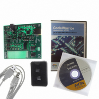
DEMO BOARD FOR 9RS08KA2
Manufacturer
Freescale Semiconductor
Series
RS08r
Type
MCUr
Datasheets
1.DEMO9RS08KA2.pdf
(136 pages)
2.DEMO9RS08KA2.pdf
(28 pages)
3.DEMO9RS08KA2.pdf
(2 pages)
4.DEMO9RS08KA2.pdf
(6 pages)
Specifications of DEMO9RS08KA2
Contents
Board, Cable, CD, Documentation, Sample ICs
Processor To Be Evaluated
RS08KA2
Data Bus Width
8 bit
Interface Type
USB
Silicon Manufacturer
Freescale
Core Architecture
RS08
Core Sub-architecture
RS08
Silicon Core Number
MC9RS08
Silicon Family Name
RS08KA
Rohs Compliant
Yes
For Use With/related Products
MC9RS08KA2
Lead Free Status / RoHS Status
Lead free / RoHS Compliant
Available stocks
Company
Part Number
Manufacturer
Quantity
Price
Company:

Part Number:
DEMO9RS08KA2
Manufacturer:
Freescale Semiconductor
Quantity:
135


Chapter 12
Development Support
12.1
Development support systems in the RS08 family include the RS08 background debug controller (BDC).
The BDC provides a single-wire debug interface to the target MCU. This interface provides a convenient
means for programming the on-chip FLASH and other nonvolatile memories. Also, the BDC is the
primary debug interface for development and allows non-intrusive access to memory data and traditional
debug features such as CPU register modify, breakpoint, and single-instruction trace commands.
In the RS08 Family, address and data bus signals are not available on external pins. Debug is done through
commands fed into the target MCU via the single-wire background debug interface, including resetting the
device without using a reset pin.
12.2
Features of the RS08 background debug controller (BDC) include:
Freescale Semiconductor
•
•
•
•
•
•
•
Uses a single pin for background debug serial communications
Non-intrusive of user memory resources; BDC registers are not located in the memory map
SYNC command to determine target communications rate
Non-intrusive commands allow access to memory resources while CPU is running user code
without stopping applications
Active background mode commands for CPU register access
GO and TRACE1 commands
BACKGROUND command can wake CPU from wait or stop modes
Introduction
Features
TARGET
USER PCB
MCU
Figure 12-1. Connecting MCU to Host for Debugging
COMMAND TRANSLATOR
MC9RS08KA2 Series Data Sheet, Rev. 4
RS08 POD
RS-232
USB, Ethernet
HOST
97
Related parts for DEMO9RS08KA2
Image
Part Number
Description
Manufacturer
Datasheet
Request
R

Part Number:
Description:
Manufacturer:
Freescale Semiconductor, Inc
Datasheet:
Part Number:
Description:
Manufacturer:
Freescale Semiconductor, Inc
Datasheet:
Part Number:
Description:
Manufacturer:
Freescale Semiconductor, Inc
Datasheet:
Part Number:
Description:
Manufacturer:
Freescale Semiconductor, Inc
Datasheet:
Part Number:
Description:
Manufacturer:
Freescale Semiconductor, Inc
Datasheet:
Part Number:
Description:
Manufacturer:
Freescale Semiconductor, Inc
Datasheet:
Part Number:
Description:
Manufacturer:
Freescale Semiconductor, Inc
Datasheet:
Part Number:
Description:
Manufacturer:
Freescale Semiconductor, Inc
Datasheet:
Part Number:
Description:
Manufacturer:
Freescale Semiconductor, Inc
Datasheet:
Part Number:
Description:
Manufacturer:
Freescale Semiconductor, Inc
Datasheet:
Part Number:
Description:
Manufacturer:
Freescale Semiconductor, Inc
Datasheet:
Part Number:
Description:
Manufacturer:
Freescale Semiconductor, Inc
Datasheet:
Part Number:
Description:
Manufacturer:
Freescale Semiconductor, Inc
Datasheet:
Part Number:
Description:
Manufacturer:
Freescale Semiconductor, Inc
Datasheet:
Part Number:
Description:
Manufacturer:
Freescale Semiconductor, Inc
Datasheet: