DEMO9RS08KA2 Freescale Semiconductor, DEMO9RS08KA2 Datasheet - Page 23
DEMO9RS08KA2
Manufacturer Part Number
DEMO9RS08KA2
Description
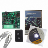
DEMO BOARD FOR 9RS08KA2
Manufacturer
Freescale Semiconductor
Series
RS08r
Type
MCUr
Datasheets
1.DEMO9RS08KA2.pdf
(136 pages)
2.DEMO9RS08KA2.pdf
(28 pages)
3.DEMO9RS08KA2.pdf
(2 pages)
4.DEMO9RS08KA2.pdf
(6 pages)
Specifications of DEMO9RS08KA2
Contents
Board, Cable, CD, Documentation, Sample ICs
Processor To Be Evaluated
RS08KA2
Data Bus Width
8 bit
Interface Type
USB
Silicon Manufacturer
Freescale
Core Architecture
RS08
Core Sub-architecture
RS08
Silicon Core Number
MC9RS08
Silicon Family Name
RS08KA
Rohs Compliant
Yes
For Use With/related Products
MC9RS08KA2
Lead Free Status / RoHS Status
Lead free / RoHS Compliant
Available stocks
Company
Part Number
Manufacturer
Quantity
Price
Company:

Part Number:
DEMO9RS08KA2
Manufacturer:
Freescale Semiconductor
Quantity:
135


Table 3-1
3.6
Stop mode is entered upon execution of a STOP instruction when the STOPE bit in the system option
register is set. In stop mode, all internal clocks to the CPU and the modules are halted. If the STOPE bit is
not set when the CPU executes a STOP instruction, the MCU will not enter stop mode and an illegal
opcode reset is forced.
Table 3-2
Upon entering stop mode, all of the clocks in the MCU are halted. The ICS is turned off by default when
the IREFSTEN bit is cleared and the voltage regulator is put in standby. The states of all of the internal
registers and logic, as well as the RAM content, are maintained. The I/O pin states are held.
Exit from stop is done by asserting RESET, any asynchronous interrupt that has been enabled, or the
real-time interrupt. The asynchronous interrupts are the KBI pins, LVD interrupt, or the ACMP interrupt.
If stop is exited by asserting the RESET pin, the MCU will be reset and program execution starts at
location $3FFD. If exited by means of an asynchronous interrupt or real-time interrupt, the next instruction
after the location where the STOP instruction was executed will be executed accordingly. It is the
responsibility of the user program to probe for the corresponding interrupt source that woke the CPU.
A separate self-clocked source (≈1 kHz) for the real-time interrupt allows a wakeup from stop mode with
no external components. When RTIS = 000, the real-time interrupt function and the 1-kHz source are
disabled. Power consumption is lower when the 1-kHz source is disabled, but in that case, the real-time
interrupt cannot wake the MCU from stop.
The trimmed 32-kHz clock in the ICS module can also be enabled for the real-time interrupt to allow a
wakeup from stop mode with no external components. The 32-kHz clock reference is enabled by setting
Freescale Semiconductor
1
2
3
Mode
Mode
ICS requires IREFSTEN = 1 and LVDE and LVDSE must be set to allow operation in stop.
If bandgap reference is required, the LVDE and LVDSE bits in the SPMSC1 must both be set before entering
stop.
If the 32-kHz trimmed clock in the ICS module is selected as the clock source for the RTI, LVDE and LVDSE bits
in the SPMSC1 must both be set before entering stop.
Stop
Wait
Stop Mode
summarizes the behavior of the MCU in wait mode.
summarizes the behavior of the MCU in stop mode.
Standby
Standby
CPU
CPU
Optionally on
Peripherals
Peripherals
Standby
Digital
Digital
MC9RS08KA2 Series Data Sheet, Rev. 4
Table 3-2. Stop Mode Behavior
Table 3-1. Wait Mode Behavior
Optionally
ICS
ICS
On
on
1
Optionally
Optionally
ACMP
ACMP
on
on
2
Regulator
Regulator
Standby
On
States held Optionally on
States held Optionally on
I/O Pins
I/O Pins
Chapter 3 Modes of Operation
RTI
RTI
3
23
Related parts for DEMO9RS08KA2
Image
Part Number
Description
Manufacturer
Datasheet
Request
R

Part Number:
Description:
Manufacturer:
Freescale Semiconductor, Inc
Datasheet:
Part Number:
Description:
Manufacturer:
Freescale Semiconductor, Inc
Datasheet:
Part Number:
Description:
Manufacturer:
Freescale Semiconductor, Inc
Datasheet:
Part Number:
Description:
Manufacturer:
Freescale Semiconductor, Inc
Datasheet:
Part Number:
Description:
Manufacturer:
Freescale Semiconductor, Inc
Datasheet:
Part Number:
Description:
Manufacturer:
Freescale Semiconductor, Inc
Datasheet:
Part Number:
Description:
Manufacturer:
Freescale Semiconductor, Inc
Datasheet:
Part Number:
Description:
Manufacturer:
Freescale Semiconductor, Inc
Datasheet:
Part Number:
Description:
Manufacturer:
Freescale Semiconductor, Inc
Datasheet:
Part Number:
Description:
Manufacturer:
Freescale Semiconductor, Inc
Datasheet:
Part Number:
Description:
Manufacturer:
Freescale Semiconductor, Inc
Datasheet:
Part Number:
Description:
Manufacturer:
Freescale Semiconductor, Inc
Datasheet:
Part Number:
Description:
Manufacturer:
Freescale Semiconductor, Inc
Datasheet:
Part Number:
Description:
Manufacturer:
Freescale Semiconductor, Inc
Datasheet:
Part Number:
Description:
Manufacturer:
Freescale Semiconductor, Inc
Datasheet: