HD64F2166VTE33 Renesas Electronics America, HD64F2166VTE33 Datasheet - Page 31
HD64F2166VTE33
Manufacturer Part Number
HD64F2166VTE33
Description
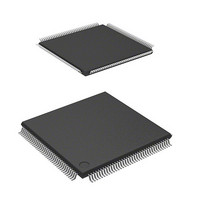
IC H8S MCU FLASH 512K 144-TQFP
Manufacturer
Renesas Electronics America
Series
H8® H8S/2100r
Specifications of HD64F2166VTE33
Core Processor
H8S/2000
Core Size
16-Bit
Speed
33MHz
Connectivity
I²C, IrDA, LPC, SCI, SmartCard
Peripherals
POR, PWM, WDT
Number Of I /o
106
Program Memory Size
512KB (512K x 8)
Program Memory Type
FLASH
Ram Size
40K x 8
Voltage - Supply (vcc/vdd)
3 V ~ 3.6 V
Data Converters
A/D 8x10b; D/A 2x8b
Oscillator Type
Internal
Operating Temperature
-20°C ~ 75°C
Package / Case
144-TQFP, 144-VQFP
Lead Free Status / RoHS Status
Contains lead / RoHS non-compliant
Eeprom Size
-
Available stocks
Company
Part Number
Manufacturer
Quantity
Price
Company:

Part Number:
HD64F2166VTE33V
Manufacturer:
Renesas
Quantity:
200
Company:
Part Number:
HD64F2166VTE33V
Manufacturer:
ON
Quantity:
75
Part Number:
HD64F2166VTE33V
Manufacturer:
RENESAS/瑞萨
Quantity:
20 000


Figure 14.11 Example of SCI Operation in Reception
Figure 14.12 Sample Serial Reception Flowchart (1)................................................................. 391
Figure 14.12 Sample Serial Reception Flowchart (2)................................................................. 392
Figure 14.13 Example of Communication Using Multiprocessor Format
Figure 14.14 Sample Multiprocessor Serial Transmission Flowchart ........................................ 395
Figure 14.15 Example of SCI Operation in Reception
Figure 14.16 Sample Multiprocessor Serial Reception Flowchart (1)........................................ 397
Figure 14.16 Sample Multiprocessor Serial Reception Flowchart (2)........................................ 398
Figure 14.17 Data Format in Synchronous Communication (LSB-First)................................... 399
Figure 14.18 Sample SCI Initialization Flowchart ..................................................................... 400
Figure 14.19 Sample SCI Transmission Operation in Clock Synchronous Mode ...................... 401
Figure 14.20 Sample Serial Transmission Flowchart ................................................................. 402
Figure 14.21 Example of SCI Receive Operation in Clock Synchronous Mode ........................ 403
Figure 14.22 Sample Serial Reception Flowchart ...................................................................... 404
Figure 14.23 Sample Flowchart of Simultaneous Serial Transmission and Reception .............. 406
Figure 14.24 Pin Connection for Smart Card Interface .............................................................. 407
Figure 14.25 Data Formats in Normal Smart Card Interface Mode............................................ 408
Figure 14.26 Direct Convention (SDIR = SINV = O/E = 0) ...................................................... 408
Figure 14.27 Inverse Convention (SDIR = SINV = O/E = 1)..................................................... 408
Figure 14.28 Receive Data Sampling Timing in Smart Card Interface Mode
Figure 14.29 Data Re-transfer Operation in SCI Transmission Mode........................................ 412
Figure 14.30 TEND Flag Set Timings during Transmission ...................................................... 412
Figure 14.31 Sample Transmission Flowchart ........................................................................... 413
Figure 14.32 Data Re-transfer Operation in SCI Reception Mode ............................................. 414
Figure 14.33 Sample Reception Flowchart................................................................................. 415
Figure 14.34 Clock Output Fixing Timing ................................................................................. 415
Figure 14.35 Clock Stop and Restart Procedure ......................................................................... 416
Figure 14.36 IrDA Block Diagram ............................................................................................. 417
Figure 14.37 IrDA Transmission and Reception ........................................................................ 418
Figure 14.38 Sample Transmission using DTC in Clock Synchronous Mode ........................... 423
Figure 14.39 Sample Flowchart for Mode Transition during Transmission............................... 424
Figure 14.40 Pin States during Transmission in Asynchronous Mode (Internal Clock)............. 425
Figure 14.41 Pin States during Transmission in Clock Synchronous Mode
Figure 14.42 Sample Flowchart for Mode Transition during Reception .................................... 426
Figure 14.43 Switching from SCK Pins to Port Pins.................................................................. 427
Figure 14.44 Prevention of Low Pulse Output at Switching from SCK Pins to Port Pins.......... 427
Figure 14.45 Block Diagram of CRC Operation Circuit ............................................................ 428
Figure 14.46 LSB-First Data Transmission ................................................................................ 430
(Example with 8-Bit Data, Parity, One Stop Bit)................................................... 389
(Transmission of Data H'AA to Receiving Station A)........................................... 394
(Example with 8-Bit Data, Multiprocessor Bit, One Stop Bit) .............................. 396
(When Clock Frequency is 372 Times the Bit Rate) ............................................. 410
(Internal Clock)...................................................................................................... 425
Rev. 3.00, 03/04, page xxix of xl
Related parts for HD64F2166VTE33
Image
Part Number
Description
Manufacturer
Datasheet
Request
R

Part Number:
Description:
KIT STARTER FOR M16C/29
Manufacturer:
Renesas Electronics America
Datasheet:

Part Number:
Description:
KIT STARTER FOR R8C/2D
Manufacturer:
Renesas Electronics America
Datasheet:

Part Number:
Description:
R0K33062P STARTER KIT
Manufacturer:
Renesas Electronics America
Datasheet:

Part Number:
Description:
KIT STARTER FOR R8C/23 E8A
Manufacturer:
Renesas Electronics America
Datasheet:

Part Number:
Description:
KIT STARTER FOR R8C/25
Manufacturer:
Renesas Electronics America
Datasheet:

Part Number:
Description:
KIT STARTER H8S2456 SHARPE DSPLY
Manufacturer:
Renesas Electronics America
Datasheet:

Part Number:
Description:
KIT STARTER FOR R8C38C
Manufacturer:
Renesas Electronics America
Datasheet:

Part Number:
Description:
KIT STARTER FOR R8C35C
Manufacturer:
Renesas Electronics America
Datasheet:

Part Number:
Description:
KIT STARTER FOR R8CL3AC+LCD APPS
Manufacturer:
Renesas Electronics America
Datasheet:
Part Number:
Description:
KIT STARTER FOR RX610
Manufacturer:
Renesas Electronics America
Datasheet:

Part Number:
Description:
KIT STARTER FOR R32C/118
Manufacturer:
Renesas Electronics America
Datasheet:

Part Number:
Description:
KIT DEV RSK-R8C/26-29
Manufacturer:
Renesas Electronics America
Datasheet:

Part Number:
Description:
KIT STARTER FOR SH7124
Manufacturer:
Renesas Electronics America
Datasheet:

Part Number:
Description:
KIT STARTER FOR H8SX/1622
Manufacturer:
Renesas Electronics America
Datasheet:

Part Number:
Description:
KIT DEV FOR SH7203
Manufacturer:
Renesas Electronics America
Datasheet: