TMPSNS-RTD1 Microchip Technology, TMPSNS-RTD1 Datasheet - Page 148
TMPSNS-RTD1
Manufacturer Part Number
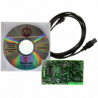
TMPSNS-RTD1
Description
BOARD EVAL PT100 RTD TEMP SENSOR
Manufacturer
Microchip Technology
Datasheets
1.MCP3301-CIMS.pdf
(32 pages)
2.PCM18XR1.pdf
(438 pages)
3.MCP6S22DM-PICTL.pdf
(43 pages)
4.TMPSNS-RTD1.pdf
(26 pages)
Specifications of TMPSNS-RTD1
Sensor Type
Temperature
Interface
USB
Embedded
Yes, MCU, 8-Bit
Utilized Ic / Part
MCP3301, MCP6S26, PIC18F2550
Processor To Be Evaluated
MCP6S26, MCP3301, MCP6024, MCP41010, PIC18F2550, TC1071, MCP6002
Data Bus Width
12 bit
Interface Type
USB
Lead Free Status / RoHS Status
Not applicable / Not applicable
Voltage - Supply
-
Sensitivity
-
Sensing Range
-
Lead Free Status / RoHS Status
Lead free / RoHS Compliant, Not applicable / Not applicable


PIC18F2455/2550/4455/4550
15.3
In Compare mode, the 16-bit CCPRx register value is
constantly compared against either the TMR1 or TMR3
register pair value. When a match occurs, the CCPx pin
can be:
• driven high
• driven low
• toggled (high-to-low or low-to-high)
• remain unchanged (that is, reflects the state of the
The action on the pin is based on the value of the mode
select bits (CCPxM3:CCPxM0). At the same time, the
interrupt flag bit, CCPxIF, is set.
15.3.1
The user must configure the CCPx pin as an output by
clearing the appropriate TRIS bit.
FIGURE 15-2:
DS39632E-page 146
I/O latch)
Note:
Compare Mode
CCP PIN CONFIGURATION
Clearing the CCP2CON register will force
the RB3 or RC1 compare output latch
(depending on device configuration) to the
default low level. This is not the PORTB or
PORTC I/O data latch.
0
1
CCPR2H
COMPARE MODE OPERATION BLOCK DIAGRAM
CCPR1H
TMR1H
TMR3H
T3CCP1
Comparator
Comparator
CCPR2L
CCPR1L
TMR1L
TMR3L
Compare
Compare
Match
Match
0
1
Set CCP1IF
T3CCP2
Set CCP2IF
(Timer1/Timer3 Reset, A/D Trigger)
(Timer1/Timer3 Reset)
15.3.2
Timer1 and/or Timer3 must be running in Timer mode,
or Synchronized Counter mode, if the CCP module is
using the compare feature. In Asynchronous Counter
mode, the compare operation may not work.
15.3.3
When the Generate Software Interrupt mode is chosen
(CCPxM3:CCPxM0 = 1010), the corresponding CCPx
pin is not affected. Only a CCP interrupt is generated,
if enabled, and the CCPxIE bit is set.
15.3.4
Both CCP modules are equipped with a Special Event
Trigger. This is an internal hardware signal generated
in Compare mode to trigger actions by other modules.
The Special Event Trigger is enabled by selecting
the
(CCPxM3:CCPxM0 = 1011).
For either CCP module, the Special Event Trigger resets
the Timer register pair for whichever timer resource is
currently assigned as the module’s time base. This
allows the CCPRx registers to serve as a programmable
Period register for either timer.
The Special Event Trigger for CCP2 can also start an
A/D conversion. In order to do this, the A/D converter
must already be enabled.
Special Event Trigger
Special Event Trigger
CCP1CON<3:0>
CCP2CON<3:0>
Compare
Output
Output
Logic
4
Logic
4
TIMER1/TIMER3 MODE SELECTION
SOFTWARE INTERRUPT MODE
SPECIAL EVENT TRIGGER
Special
S
R
S
R
Q
Q
© 2009 Microchip Technology Inc.
Output Enable
Output Enable
Event
TRIS
TRIS
CCP1 pin
Trigger
CCP2 pin
mode
Related parts for TMPSNS-RTD1
Image
Part Number
Description
Manufacturer
Datasheet
Request
R

Part Number:
Description:
Manufacturer:
Microchip Technology Inc.
Datasheet:
Part Number:
Description:
Manufacturer:
Microchip Technology Inc.
Datasheet:
Part Number:
Description:
Manufacturer:
Microchip Technology Inc.
Datasheet:
Part Number:
Description:
Manufacturer:
Microchip Technology Inc.
Datasheet:
Part Number:
Description:
Manufacturer:
Microchip Technology Inc.
Datasheet:
Part Number:
Description:
Manufacturer:
Microchip Technology Inc.
Datasheet:
Part Number:
Description:
Manufacturer:
Microchip Technology Inc.
Datasheet:
Part Number:
Description:
Manufacturer:
Microchip Technology Inc.
Datasheet: