TMPSNS-RTD1 Microchip Technology, TMPSNS-RTD1 Datasheet - Page 47
TMPSNS-RTD1
Manufacturer Part Number
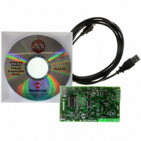
TMPSNS-RTD1
Description
BOARD EVAL PT100 RTD TEMP SENSOR
Manufacturer
Microchip Technology
Datasheets
1.MCP3301-CIMS.pdf
(32 pages)
2.PCM18XR1.pdf
(438 pages)
3.MCP6S22DM-PICTL.pdf
(43 pages)
4.TMPSNS-RTD1.pdf
(26 pages)
Specifications of TMPSNS-RTD1
Sensor Type
Temperature
Interface
USB
Embedded
Yes, MCU, 8-Bit
Utilized Ic / Part
MCP3301, MCP6S26, PIC18F2550
Processor To Be Evaluated
MCP6S26, MCP3301, MCP6024, MCP41010, PIC18F2550, TC1071, MCP6002
Data Bus Width
12 bit
Interface Type
USB
Lead Free Status / RoHS Status
Not applicable / Not applicable
Voltage - Supply
-
Sensitivity
-
Sensing Range
-
Lead Free Status / RoHS Status
Lead free / RoHS Compliant, Not applicable / Not applicable


4.0
The PIC18F2455/2550/4455/4550 devices differentiate
between various kinds of Reset:
a)
b)
c)
d)
e)
f)
g)
h)
This section discusses Resets generated by MCLR,
POR and BOR and covers the operation of the various
start-up timers. Stack Reset events are covered in
Section 5.1.2.4 “Stack Full and Underflow Resets”.
WDT Resets are covered in Section 25.2 “Watchdog
Timer (WDT)”.
FIGURE 4-1:
© 2009 Microchip Technology Inc.
Note 1: This is the low-frequency INTRC source from the internal oscillator block.
OSC1
MCLR
V
Power-on Reset (POR)
MCLR Reset during normal operation
MCLR Reset during power-managed modes
Watchdog Timer (WDT) Reset (during
execution)
Programmable Brown-out Reset (BOR)
RESET Instruction
Stack Full Reset
Stack Underflow Reset
DD
2: See Table 4-2 for time-out situations.
RESET
Instruction
INTRC
RESET
OST/PWRT
Pointer
32 μs
Stack
( )_IDLE
Brown-out
V
Time-out
(1)
Detect
Sleep
DD
WDT
Reset
Rise
OST
PWRT
Stack Full/Underflow Reset
SIMPLIFIED BLOCK DIAGRAM OF ON-CHIP RESET CIRCUIT
External Reset
MCLRE
10-Bit Ripple Counter
11-Bit Ripple Counter
POR Pulse
BOREN
1024 Cycles
65.5 ms
PIC18F2455/2550/4455/4550
A simplified block diagram of the on-chip Reset circuit
is shown in Figure 4-1.
4.1
Device Reset events are tracked through the RCON
register (Register 4-1). The lower five bits of the regis-
ter indicate that a specific Reset event has occurred. In
most cases, these bits can only be cleared by the event
and must be set by the application after the event. The
state of these flag bits, taken together, can be read to
indicate the type of Reset that just occurred. This is
described in more detail in Section 4.6 “Reset State
of Registers”.
The RCON register also has control bits for setting
interrupt priority (IPEN) and software control of the
BOR (SBOREN). Interrupt priority is discussed in
Section 9.0
Section 4.4 “Brown-out Reset (BOR)”.
RCON Register
“Interrupts”.
S
R
BOR
Q
DS39632E-page 45
is
Enable OST
Enable PWRT
Chip_Reset
covered
(2)
in
Related parts for TMPSNS-RTD1
Image
Part Number
Description
Manufacturer
Datasheet
Request
R

Part Number:
Description:
Manufacturer:
Microchip Technology Inc.
Datasheet:
Part Number:
Description:
Manufacturer:
Microchip Technology Inc.
Datasheet:
Part Number:
Description:
Manufacturer:
Microchip Technology Inc.
Datasheet:
Part Number:
Description:
Manufacturer:
Microchip Technology Inc.
Datasheet:
Part Number:
Description:
Manufacturer:
Microchip Technology Inc.
Datasheet:
Part Number:
Description:
Manufacturer:
Microchip Technology Inc.
Datasheet:
Part Number:
Description:
Manufacturer:
Microchip Technology Inc.
Datasheet:
Part Number:
Description:
Manufacturer:
Microchip Technology Inc.
Datasheet: