TMPSNS-RTD1 Microchip Technology, TMPSNS-RTD1 Datasheet - Page 369
TMPSNS-RTD1
Manufacturer Part Number
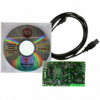
TMPSNS-RTD1
Description
BOARD EVAL PT100 RTD TEMP SENSOR
Manufacturer
Microchip Technology
Datasheets
1.MCP3301-CIMS.pdf
(32 pages)
2.PCM18XR1.pdf
(438 pages)
3.MCP6S22DM-PICTL.pdf
(43 pages)
4.TMPSNS-RTD1.pdf
(26 pages)
Specifications of TMPSNS-RTD1
Sensor Type
Temperature
Interface
USB
Embedded
Yes, MCU, 8-Bit
Utilized Ic / Part
MCP3301, MCP6S26, PIC18F2550
Processor To Be Evaluated
MCP6S26, MCP3301, MCP6024, MCP41010, PIC18F2550, TC1071, MCP6002
Data Bus Width
12 bit
Interface Type
USB
Lead Free Status / RoHS Status
Not applicable / Not applicable
Voltage - Supply
-
Sensitivity
-
Sensing Range
-
Lead Free Status / RoHS Status
Lead free / RoHS Compliant, Not applicable / Not applicable


28.0
Absolute Maximum Ratings
Ambient temperature under bias.............................................................................................................. .-40°C to +85°C
Storage temperature .............................................................................................................................. -65°C to +150°C
Voltage on any pin with respect to V
Voltage on V
Voltage on MCLR with respect to V
Total power dissipation (Note 1) ...............................................................................................................................1.0W
Maximum current out of V
Maximum current into V
Input clamp current, I
Output clamp current, I
Maximum output current sunk by any I/O pin..........................................................................................................25 mA
Maximum output current sourced by any I/O pin ....................................................................................................25 mA
Maximum current sunk by all ports .......................................................................................................................200 mA
Maximum current sourced by all ports ..................................................................................................................200 mA
© 2009 Microchip Technology Inc.
† NOTICE: Stresses above those listed under “Absolute Maximum Ratings” may cause permanent damage to the
device. This is a stress rating only and functional operation of the device at those or any other conditions above those
indicated in the operation listings of this specification is not implied. Exposure to maximum rating conditions for
extended periods may affect device reliability.
Note 1: Power dissipation is calculated as follows:
2: Voltage spikes below V
3: When the internal USB regulator is enabled or V
ELECTRICAL CHARACTERISTICS
Pdis = V
latch-up. Thus, a series resistor of 50-100Ω should be used when applying a “low” level to the MCLR/V
RE3 pin, rather than pulling this pin directly to V
to (V
DD
with respect to V
USB
DD
+ 0.3V) with respect to V
IK
OK
x {I
(V
DD
I
SS
(V
DD
< 0 or V
pin ..............................................................................................................................250 mA
O
pin ...........................................................................................................................300 mA
– ∑ I
< 0 or V
SS
OH
I
SS
SS
SS
> V
(†)
......................................................................................................... -0.3V to +7.5V
} + ∑ {(V
(Note 2) ......................................................................................... 0V to +13.25V
O
at the MCLR/V
(except V
DD
> V
)...................................................................................................................... ±20 mA
DD
SS
PIC18F2455/2550/4455/4550
DD
) .............................................................................................................. ±20 mA
.
DD
– V
and MCLR) (Note 3) ..................................... -0.3V to (V
OH
PP
) x I
/RE3 pin, inducing currents greater than 80 mA, may cause
USB
OH
SS
} + ∑(V
.
is powered externally, RC4 and RC5 are limited to -0.3V
OL
x I
OL
)
DS39632E-page 367
DD
+ 0.3V)
PP
/
Related parts for TMPSNS-RTD1
Image
Part Number
Description
Manufacturer
Datasheet
Request
R

Part Number:
Description:
Manufacturer:
Microchip Technology Inc.
Datasheet:
Part Number:
Description:
Manufacturer:
Microchip Technology Inc.
Datasheet:
Part Number:
Description:
Manufacturer:
Microchip Technology Inc.
Datasheet:
Part Number:
Description:
Manufacturer:
Microchip Technology Inc.
Datasheet:
Part Number:
Description:
Manufacturer:
Microchip Technology Inc.
Datasheet:
Part Number:
Description:
Manufacturer:
Microchip Technology Inc.
Datasheet:
Part Number:
Description:
Manufacturer:
Microchip Technology Inc.
Datasheet:
Part Number:
Description:
Manufacturer:
Microchip Technology Inc.
Datasheet: