TMPSNS-RTD1 Microchip Technology, TMPSNS-RTD1 Datasheet - Page 171
TMPSNS-RTD1
Manufacturer Part Number
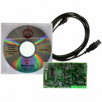
TMPSNS-RTD1
Description
BOARD EVAL PT100 RTD TEMP SENSOR
Manufacturer
Microchip Technology
Datasheets
1.MCP3301-CIMS.pdf
(32 pages)
2.PCM18XR1.pdf
(438 pages)
3.MCP6S22DM-PICTL.pdf
(43 pages)
4.TMPSNS-RTD1.pdf
(26 pages)
Specifications of TMPSNS-RTD1
Sensor Type
Temperature
Interface
USB
Embedded
Yes, MCU, 8-Bit
Utilized Ic / Part
MCP3301, MCP6S26, PIC18F2550
Processor To Be Evaluated
MCP6S26, MCP3301, MCP6024, MCP41010, PIC18F2550, TC1071, MCP6002
Data Bus Width
12 bit
Interface Type
USB
Lead Free Status / RoHS Status
Not applicable / Not applicable
Voltage - Supply
-
Sensitivity
-
Sensing Range
-
Lead Free Status / RoHS Status
Lead free / RoHS Compliant, Not applicable / Not applicable


TABLE 17-1:
TABLE 17-2:
The UOE signal toggles the state of the external trans-
ceiver. This line is pulled low by the device to enable
the transmission of data from the SIE to an external
device.
17.2.2.3
The PIC18FX455/X550 devices have built-in pull-up
resistors designed to meet the requirements for
low-speed and full-speed USB. The UPUEN bit
(UCFG<4>) enables the internal pull-ups. Figure 17-1
shows the pull-ups and their control.
17.2.2.4
External pull-up may also be used if the internal resis-
tors are not used. The V
D+ or D-. The pull-up resistor must be 1.5 kΩ (±5%) as
required by the USB specifications. Figure 17-3 shows
an example.
FIGURE 17-3:
© 2009 Microchip Technology Inc.
VPO
VP
0
0
1
1
0
0
1
1
Note:
Microcontroller
PIC
VMO
VM
The above setting shows a typical connection
for a full-speed configuration using an on-chip
regulator and an external pull-up resistor.
0
1
0
1
0
1
0
1
®
Internal Pull-up Resistors
External Pull-up Resistors
V
USB
D+
D-
DIFFERENTIAL OUTPUTS TO
TRANSCEIVER
SINGLE-ENDED INPUTS
FROM TRANSCEIVER
EXTERNAL CIRCUITRY
USB
Single-Ended Zero
Single-Ended Zero
1.5 kΩ
Illegal Condition
Differential ‘0’
Differential ‘1’
pin may be used to pull up
High Speed
Low Speed
Bus State
Bus State
Error
Controller/HUB
Host
PIC18F2455/2550/4455/4550
17.2.2.5
The usage of ping-pong buffers is configured using the
PPB1:PPB0 bits. Refer to Section 17.4.4 “Ping-Pong
Buffering” for a complete explanation of the ping-pong
buffers.
17.2.2.6
The USB OE monitor provides indication as to whether
the SIE is listening to the bus or actively driving the bus.
This is enabled by default when using an external
transceiver or when UCFG<6> = 1.
The USB OE monitoring is useful for initial system
debugging, as well as scope triggering during eye
pattern generation tests.
17.2.2.7
An automatic eye pattern test can be generated by the
module when the UCFG<7> bit is set. The eye pattern
output will be observable based on module settings,
meaning that the user is first responsible for configuring
the SIE clock settings, pull-up resistor and Transceiver
mode. In addition, the module has to be enabled.
Once UTEYE is set, the module emulates a switch from
a receive to transmit state and will start transmitting a
J-K-J-K bit sequence (K-J-K-J for full speed). The
sequence will be repeated indefinitely while the Eye
Pattern Test mode is enabled.
Note that this bit should never be set while the module
is connected to an actual USB system. This test mode
is intended for board verification to aid with USB certi-
fication tests. It is intended to show a system developer
the noise integrity of the USB signals which can be
affected by board traces, impedance mismatches and
proximity to other system components. It does not
properly test the transition from a receive to a transmit
state. Although the eye pattern is not meant to replace
the more complex USB certification test, it should aid
during first order system debugging.
Ping-Pong Buffer Configuration
USB Output Enable Monitor
Eye Pattern Test Enable
DS39632E-page 169
Related parts for TMPSNS-RTD1
Image
Part Number
Description
Manufacturer
Datasheet
Request
R

Part Number:
Description:
Manufacturer:
Microchip Technology Inc.
Datasheet:
Part Number:
Description:
Manufacturer:
Microchip Technology Inc.
Datasheet:
Part Number:
Description:
Manufacturer:
Microchip Technology Inc.
Datasheet:
Part Number:
Description:
Manufacturer:
Microchip Technology Inc.
Datasheet:
Part Number:
Description:
Manufacturer:
Microchip Technology Inc.
Datasheet:
Part Number:
Description:
Manufacturer:
Microchip Technology Inc.
Datasheet:
Part Number:
Description:
Manufacturer:
Microchip Technology Inc.
Datasheet:
Part Number:
Description:
Manufacturer:
Microchip Technology Inc.
Datasheet: