TMPSNS-RTD1 Microchip Technology, TMPSNS-RTD1 Datasheet - Page 27
TMPSNS-RTD1
Manufacturer Part Number
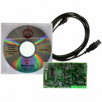
TMPSNS-RTD1
Description
BOARD EVAL PT100 RTD TEMP SENSOR
Manufacturer
Microchip Technology
Datasheets
1.MCP3301-CIMS.pdf
(32 pages)
2.PCM18XR1.pdf
(438 pages)
3.MCP6S22DM-PICTL.pdf
(43 pages)
4.TMPSNS-RTD1.pdf
(26 pages)
Specifications of TMPSNS-RTD1
Sensor Type
Temperature
Interface
USB
Embedded
Yes, MCU, 8-Bit
Utilized Ic / Part
MCP3301, MCP6S26, PIC18F2550
Processor To Be Evaluated
MCP6S26, MCP3301, MCP6024, MCP41010, PIC18F2550, TC1071, MCP6002
Data Bus Width
12 bit
Interface Type
USB
Lead Free Status / RoHS Status
Not applicable / Not applicable
Voltage - Supply
-
Sensitivity
-
Sensing Range
-
Lead Free Status / RoHS Status
Lead free / RoHS Compliant, Not applicable / Not applicable


2.2.2
In HS, HSPLL, XT and XTPLL Oscillator modes, a
crystal or ceramic resonator is connected to the OSC1
and OSC2 pins to establish oscillation. Figure 2-2
shows the pin connections.
The oscillator design requires the use of a parallel cut
crystal.
FIGURE 2-2:
© 2009 Microchip Technology Inc.
Note 1: See Table 2-1 and Table 2-2 for initial values of
Note:
C1
C2
2: A series resistor (R
3: R
(1)
(1)
C1 and C2.
strip cut crystals.
CRYSTAL OSCILLATOR/CERAMIC
RESONATORS
Use of a series cut crystal may give a fre-
quency out of the crystal manufacturer’s
specifications.
F
varies with the oscillator mode chosen.
XTAL
R
S
(2)
OSC2
OSC1
CRYSTAL/CERAMIC
RESONATOR OPERATION
(XT, HS OR HSPLL
CONFIGURATION)
S
) may be required for AT
R
F
(3)
PIC18FXXXX
Sleep
PIC18F2455/2550/4455/4550
To
Internal
Logic
TABLE 2-1:
Capacitor values are for design guidance only.
These capacitors were tested with the resonators
listed below for basic start-up and operation. These
values are not optimized.
Different capacitor values may be required to produce
acceptable oscillator operation. The user should test
the performance of the oscillator over the expected
V
See the notes following Table 2-2 for additional
information.
When using ceramic resonators with frequencies
above 3.5 MHz, HS mode is recommended over XT
mode. HS mode may be used at any V
the controller is rated. If HS is selected, the gain of the
oscillator may overdrive the resonator. Therefore, a
series resistor should be placed between the OSC2
pin and the resonator. As a good starting point, the
recommended value of RS is 330 Ω.
DD
Mode
HS
XT
and temperature range for the application.
Typical Capacitor Values Used:
16.0 MHz
4.0 MHz
8.0 MHz
Freq
Resonators Used:
CAPACITOR SELECTION FOR
CERAMIC RESONATORS
16.0 MHz
4.0 MHz
8.0 MHz
OSC1
33 pF
27 pF
22 pF
DS39632E-page 25
DD
for which
OSC2
33 pF
27 pF
22 pF
Related parts for TMPSNS-RTD1
Image
Part Number
Description
Manufacturer
Datasheet
Request
R

Part Number:
Description:
Manufacturer:
Microchip Technology Inc.
Datasheet:
Part Number:
Description:
Manufacturer:
Microchip Technology Inc.
Datasheet:
Part Number:
Description:
Manufacturer:
Microchip Technology Inc.
Datasheet:
Part Number:
Description:
Manufacturer:
Microchip Technology Inc.
Datasheet:
Part Number:
Description:
Manufacturer:
Microchip Technology Inc.
Datasheet:
Part Number:
Description:
Manufacturer:
Microchip Technology Inc.
Datasheet:
Part Number:
Description:
Manufacturer:
Microchip Technology Inc.
Datasheet:
Part Number:
Description:
Manufacturer:
Microchip Technology Inc.
Datasheet: