DEMO9S08EL32 Freescale Semiconductor, DEMO9S08EL32 Datasheet - Page 188
DEMO9S08EL32
Manufacturer Part Number
DEMO9S08EL32
Description
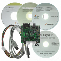
BOARD DEMO FOR 9S08 EL MCU
Manufacturer
Freescale Semiconductor
Type
MCUr
Datasheets
1.DEMO9S08EL32.pdf
(356 pages)
2.DEMO9S08EL32.pdf
(14 pages)
3.DEMO9S08EL32.pdf
(2 pages)
Specifications of DEMO9S08EL32
Contents
Evaluation Board
Processor To Be Evaluated
MC9S08EL32
Data Bus Width
8 bit
Interface Type
RS-232, USB
Operating Supply Voltage
12 V
Silicon Manufacturer
Freescale
Core Architecture
HCS08
Core Sub-architecture
HCS08
Silicon Core Number
MC9S08
Silicon Family Name
S08EL
Rohs Compliant
Yes
For Use With/related Products
MC9S08EL32
Lead Free Status / RoHS Status
Lead free / RoHS Compliant


entering SLIC stop mode, any activity on the network will cause the SLIC module to exit SLIC stop mode
and generate an unmaskable interrupt of the CPU. This wakeup interrupt state is reflected in the SLCSV,
encoded as the highest priority interrupt. This interrupt can be cleared by the CPU with a read of the
SLCSV and clearing of the SLCF interrupt flag. Depending upon which low-power mode instruction the
CPU executes to cause the SLIC module to enter SLIC stop, the message which wakes up the SLIC module
(and the CPU) may or may not be received.
There are two different possibilities:
12.1.2.8
The SLIC module operates in the same manner in all normal and emulation modes. All SLIC module
registers can be read and written except those that are reserved, unimplemented, or write once. The user
must be careful not to unintentionally change reserved bits to avoid unexpected SLIC module behavior.
12.1.2.9
Some aspects of SLIC module operation can be modified in special test mode. This mode is reserved for
internal use only.
12.1.2.10 Low-Power Options
The SLIC module can save power in disabled, wait, and stop modes.
190
1. Wakeup from SLIC Stop with CPU in STOP
2. Wakeup from SLIC Stop with CPU in WAIT. If the CPU executes the WAIT instruction and the
When the CPU executes the STOP instruction, all clocks in the MCU, including clocks to the SLIC
module, are turned off. Therefore, the message which wakes up the SLIC module and the CPU
from stop mode will not be received. This is due primarily to the amount of time required for the
MCU's oscillator to stabilize before the clocks can be applied internally to the other MCU modules,
including the SLIC module.
SLIC module enters the stop mode (SLCWCM = 1), the clocks to the SLIC module are turned off,
but the clocks in the MCU continue to run. Therefore, the message which wakes up the SLIC
module from stop and the CPU from wait mode will be received correctly by the SLIC module.
This is because very little time is required for the CPU to turn the clocks to the SLIC module back
on after the wakeup interrupt occurs.
Normal and Emulation Mode Operation
Special Mode Operation
While the SLIC module will correctly receive a message which arrives
when the SLIC module is in stop or wait mode and the MCU is in wait
mode, if the user enters this mode while a message is being received, the
data in the message will become corrupted. This is due to the steps required
for the SLIC module to resume operation upon exiting stop or wait mode,
and its subsequent resynchronization with the LIN bus.
MC9S08EL32 Series and MC9S08SL16 Series Data Sheet, Rev. 3
NOTE
Freescale Semiconductor
Related parts for DEMO9S08EL32
Image
Part Number
Description
Manufacturer
Datasheet
Request
R

Part Number:
Description:
Manufacturer:
Freescale Semiconductor, Inc
Datasheet:
Part Number:
Description:
Manufacturer:
Freescale Semiconductor, Inc
Datasheet:
Part Number:
Description:
Manufacturer:
Freescale Semiconductor, Inc
Datasheet:
Part Number:
Description:
Manufacturer:
Freescale Semiconductor, Inc
Datasheet:
Part Number:
Description:
Manufacturer:
Freescale Semiconductor, Inc
Datasheet:
Part Number:
Description:
Manufacturer:
Freescale Semiconductor, Inc
Datasheet:
Part Number:
Description:
Manufacturer:
Freescale Semiconductor, Inc
Datasheet:
Part Number:
Description:
Manufacturer:
Freescale Semiconductor, Inc
Datasheet:
Part Number:
Description:
Manufacturer:
Freescale Semiconductor, Inc
Datasheet:
Part Number:
Description:
Manufacturer:
Freescale Semiconductor, Inc
Datasheet:
Part Number:
Description:
Manufacturer:
Freescale Semiconductor, Inc
Datasheet:
Part Number:
Description:
Manufacturer:
Freescale Semiconductor, Inc
Datasheet:
Part Number:
Description:
Manufacturer:
Freescale Semiconductor, Inc
Datasheet:
Part Number:
Description:
Manufacturer:
Freescale Semiconductor, Inc
Datasheet:
Part Number:
Description:
Manufacturer:
Freescale Semiconductor, Inc
Datasheet: