DEMO9S08EL32 Freescale Semiconductor, DEMO9S08EL32 Datasheet - Page 299
DEMO9S08EL32
Manufacturer Part Number
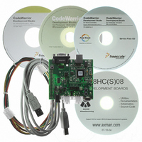
DEMO9S08EL32
Description
BOARD DEMO FOR 9S08 EL MCU
Manufacturer
Freescale Semiconductor
Type
MCUr
Datasheets
1.DEMO9S08EL32.pdf
(356 pages)
2.DEMO9S08EL32.pdf
(14 pages)
3.DEMO9S08EL32.pdf
(2 pages)
Specifications of DEMO9S08EL32
Contents
Evaluation Board
Processor To Be Evaluated
MC9S08EL32
Data Bus Width
8 bit
Interface Type
RS-232, USB
Operating Supply Voltage
12 V
Silicon Manufacturer
Freescale
Core Architecture
HCS08
Core Sub-architecture
HCS08
Silicon Core Number
MC9S08
Silicon Family Name
S08EL
Rohs Compliant
Yes
For Use With/related Products
MC9S08EL32
Lead Free Status / RoHS Status
Lead free / RoHS Compliant


All TPM interrupts are listed in
that can block the interrupt request from leaving the TPM and getting recognized by the separate interrupt
processing logic.
The TPM module will provide a high-true interrupt signal. Vectors and priorities are determined at chip
integration time in the interrupt module so refer to the user’s guide for the interrupt module or to the chip’s
complete documentation for details.
16.6.2
For each interrupt source in the TPM, a flag bit is set upon recognition of the interrupt condition such as
timer overflow, channel-input capture, or output-compare events. This flag may be read (polled) by
software to determine that the action has occurred, or an associated enable bit (TOIE or CHnIE) can be set
to enable hardware interrupt generation. While the interrupt enable bit is set, a static interrupt will generate
whenever the associated interrupt flag equals one. The user’s software must perform a sequence of steps
to clear the interrupt flag before returning from the interrupt-service routine.
TPM interrupt flags are cleared by a two-step process including a read of the flag bit while it is set (1)
followed by a write of zero (0) to the bit. If a new event is detected between these two steps, the sequence
is reset and the interrupt flag remains set after the second step to avoid the possibility of missing the new
event.
16.6.2.1
The meaning and details of operation for TOF interrupts varies slightly depending upon the mode of
operation of the TPM system (general purpose timing functions versus center-aligned PWM operation).
The flag is cleared by the two step sequence described above.
16.6.2.1.1
Normally TOF is set when the timer counter changes from 0xFFFF to 0x0000. When the TPM is not
configured for center-aligned PWM (CPWMS=0), TOF gets set when the timer counter changes from the
terminal count (the value in the modulo register) to 0x0000. This case corresponds to the normal meaning
of counter overflow.
Freescale Semiconductor
Description of Interrupt Operation
Interrupt
Timer Overflow Interrupt (TOF) Description
CHnF
TOF
Normal Case
MC9S08EL32 Series and MC9S08SL16 Series Data Sheet, Rev. 3
Enable
CHnIE
Local
TOIE
Table 16-9
Counter overflow
Channel event
Table 16-9. Interrupt Summary
Source
which shows the interrupt name, the name of any local enable
Set each time the timer counter reaches its terminal
count (at transition to next count value which is
usually 0x0000)
An input capture or output compare event took
place on channel n
Description
Timer/PWM Module (S08TPMV3)
301
Related parts for DEMO9S08EL32
Image
Part Number
Description
Manufacturer
Datasheet
Request
R

Part Number:
Description:
Manufacturer:
Freescale Semiconductor, Inc
Datasheet:
Part Number:
Description:
Manufacturer:
Freescale Semiconductor, Inc
Datasheet:
Part Number:
Description:
Manufacturer:
Freescale Semiconductor, Inc
Datasheet:
Part Number:
Description:
Manufacturer:
Freescale Semiconductor, Inc
Datasheet:
Part Number:
Description:
Manufacturer:
Freescale Semiconductor, Inc
Datasheet:
Part Number:
Description:
Manufacturer:
Freescale Semiconductor, Inc
Datasheet:
Part Number:
Description:
Manufacturer:
Freescale Semiconductor, Inc
Datasheet:
Part Number:
Description:
Manufacturer:
Freescale Semiconductor, Inc
Datasheet:
Part Number:
Description:
Manufacturer:
Freescale Semiconductor, Inc
Datasheet:
Part Number:
Description:
Manufacturer:
Freescale Semiconductor, Inc
Datasheet:
Part Number:
Description:
Manufacturer:
Freescale Semiconductor, Inc
Datasheet:
Part Number:
Description:
Manufacturer:
Freescale Semiconductor, Inc
Datasheet:
Part Number:
Description:
Manufacturer:
Freescale Semiconductor, Inc
Datasheet:
Part Number:
Description:
Manufacturer:
Freescale Semiconductor, Inc
Datasheet:
Part Number:
Description:
Manufacturer:
Freescale Semiconductor, Inc
Datasheet: