DEMO9S08EL32 Freescale Semiconductor, DEMO9S08EL32 Datasheet - Page 229
DEMO9S08EL32
Manufacturer Part Number
DEMO9S08EL32
Description
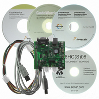
BOARD DEMO FOR 9S08 EL MCU
Manufacturer
Freescale Semiconductor
Type
MCUr
Datasheets
1.DEMO9S08EL32.pdf
(356 pages)
2.DEMO9S08EL32.pdf
(14 pages)
3.DEMO9S08EL32.pdf
(2 pages)
Specifications of DEMO9S08EL32
Contents
Evaluation Board
Processor To Be Evaluated
MC9S08EL32
Data Bus Width
8 bit
Interface Type
RS-232, USB
Operating Supply Voltage
12 V
Silicon Manufacturer
Freescale
Core Architecture
HCS08
Core Sub-architecture
HCS08
Silicon Core Number
MC9S08
Silicon Family Name
S08EL
Rohs Compliant
Yes
For Use With/related Products
MC9S08EL32
Lead Free Status / RoHS Status
Lead free / RoHS Compliant


12.6.18.2 Digital Filter Performance
The performance of the digital filter is best described in the time domain rather than the frequency domain.
If the signal on the SLCRX signal transitions, then there will be a delay before that transition appears at
the filtered Rx data output signal. This delay will be between 15 and 16 clock periods, depending on where
the transition occurs with respect to the sampling points. This ‘filter delay’ is not an issue for SLIC
operation, as there is no need for message arbitration.
The effect of random noise on the SLCRX signal depends on the characteristics of the noise itself. Narrow
noise pulses on the SLCRX signal will be completely ignored if they are shorter than the filter delay. This
provides a degree of low-pass filtering.
and the consequential effect on the filter delay. This filter delay value indicates that for a particular setup,
only pulses of which are greater than the filter delay will pass the filter.
For example, if the frequency of the SLIC clock (f
clock is 313 ns. With a receive filter prescaler setting of division by 3, the resulting maximum filter delay
in the absence of noise will be 15.00 μs. By simply changing the prescaler of the receive filter, the user can
then select alternatively 5 μs, 10 μs, or 20 μs as a minimum filter delay according to the systems
requirements.
If noise occurs during a symbol transition, the detection of that transition may be delayed by an amount
equal to the length of the noise burst. This is just a reflection of the uncertainty of where the transition is
truly occurring within the noise.
Freescale Semiconductor
The user must always account for the worst case bit timing of their LIN bus
when configuring the digital receive filter, especially if running at faster
speeds. Ground offset and other physical layer conditions can cause
shortening of bits as seen at the digital receive pin, for example. If these
shortened bit lengths are less than the filter delay, the bits will be interpreted
by the filter as noise and will be blocked, even though the nominal bit timing
might be greater than the filter delay.
MC9S08EL32 Series and MC9S08SL16 Series Data Sheet, Rev. 3
Figure 12-22
NOTE
SLIC
shows the configuration of the digital receive filter
) is 3.2 MHz, then the period (t
SLIC
) is of the SLIC
231
Related parts for DEMO9S08EL32
Image
Part Number
Description
Manufacturer
Datasheet
Request
R

Part Number:
Description:
Manufacturer:
Freescale Semiconductor, Inc
Datasheet:
Part Number:
Description:
Manufacturer:
Freescale Semiconductor, Inc
Datasheet:
Part Number:
Description:
Manufacturer:
Freescale Semiconductor, Inc
Datasheet:
Part Number:
Description:
Manufacturer:
Freescale Semiconductor, Inc
Datasheet:
Part Number:
Description:
Manufacturer:
Freescale Semiconductor, Inc
Datasheet:
Part Number:
Description:
Manufacturer:
Freescale Semiconductor, Inc
Datasheet:
Part Number:
Description:
Manufacturer:
Freescale Semiconductor, Inc
Datasheet:
Part Number:
Description:
Manufacturer:
Freescale Semiconductor, Inc
Datasheet:
Part Number:
Description:
Manufacturer:
Freescale Semiconductor, Inc
Datasheet:
Part Number:
Description:
Manufacturer:
Freescale Semiconductor, Inc
Datasheet:
Part Number:
Description:
Manufacturer:
Freescale Semiconductor, Inc
Datasheet:
Part Number:
Description:
Manufacturer:
Freescale Semiconductor, Inc
Datasheet:
Part Number:
Description:
Manufacturer:
Freescale Semiconductor, Inc
Datasheet:
Part Number:
Description:
Manufacturer:
Freescale Semiconductor, Inc
Datasheet:
Part Number:
Description:
Manufacturer:
Freescale Semiconductor, Inc
Datasheet: