DEMO9S08EL32 Freescale Semiconductor, DEMO9S08EL32 Datasheet - Page 203
DEMO9S08EL32
Manufacturer Part Number
DEMO9S08EL32
Description
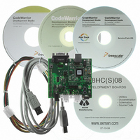
BOARD DEMO FOR 9S08 EL MCU
Manufacturer
Freescale Semiconductor
Type
MCUr
Datasheets
1.DEMO9S08EL32.pdf
(356 pages)
2.DEMO9S08EL32.pdf
(14 pages)
3.DEMO9S08EL32.pdf
(2 pages)
Specifications of DEMO9S08EL32
Contents
Evaluation Board
Processor To Be Evaluated
MC9S08EL32
Data Bus Width
8 bit
Interface Type
RS-232, USB
Operating Supply Voltage
12 V
Silicon Manufacturer
Freescale
Core Architecture
HCS08
Core Sub-architecture
HCS08
Silicon Core Number
MC9S08
Silicon Family Name
S08EL
Rohs Compliant
Yes
For Use With/related Products
MC9S08EL32
Lead Free Status / RoHS Status
Lead free / RoHS Compliant


12.6.1
The HEADER section of all LIN messages is transmitted by the master node in the network and contains
synchronization data, as well as the identifier to define what information is to be contained in the message
frame. Formally, the header is comprised of three parts:
The first two components are present to allow the LIN slave nodes to recognize the beginning of the
message frame and derive the bit rate of the master module.
The SYNCH BREAK allows the slave to see the beginning of a message frame on the bus. The SLIC
module can receive a standard 10-bit break character for the SYNCH BREAK, or any break symbol 10 or
more bit times in length. This encompasses the LIN requirement of 13 or more bits of length for the
SYNCH BREAK character.
The SYNCH BYTE is always a 0x55 data byte, providing five falling edges for the slave to derive the bit
rate of the master node.
The identifier byte indicates to the slave what is the nature of the data in the message frame. This data
might be supplied from either the master node or the slave node, as determined at system design time. The
slave node must read this identifier, check for parity errors, and determine whether it is to send or receive
data in the data field.
More information on the HEADER is contained in
12.6.2
The data field is comprised of standard bytes (eight data bits, no parity, one stop bit) of data, from 0–8
bytes for normal LIN frames and greater than eight bytes for extended LIN frames. The SLIC module will
either transmit or receive these bytes, depending upon the user code interpretation of the identifier byte.
Data is always transmitted into the data field least significant byte (LSB) first.
The SLIC module can automatically handle up to 64 bytes in extended LIN message frames without
significantly changing program execution.
Freescale Semiconductor
1. SYNCH BREAK
2. SYNCH BYTE (0x55)
3. IDENTIFIER FIELD
SYNCH
BREAK
HEADER
LIN Message Frame Header
LIN Data Field
SYNCH
0x55
13 OR MORE BITS (LIN 1.3)
BYTE
IDENT
FIELD
MC9S08EL32 Series and MC9S08SL16 Series Data Sheet, Rev. 3
DATA
FIELD
0
Figure 12-13. Typical LIN MESSAGE FRAME
FIELD
DATA
1
FIELD
DATA
2
Section 12.6.7.1, “LIN Message
FIELD
DATA
DATA
3
FIELD
DATA
4
FIELD
DATA
5
FIELD
DATA
6
Headers.”
FIELD
DATA
7
CHECKSUM
FIELD
205
Related parts for DEMO9S08EL32
Image
Part Number
Description
Manufacturer
Datasheet
Request
R

Part Number:
Description:
Manufacturer:
Freescale Semiconductor, Inc
Datasheet:
Part Number:
Description:
Manufacturer:
Freescale Semiconductor, Inc
Datasheet:
Part Number:
Description:
Manufacturer:
Freescale Semiconductor, Inc
Datasheet:
Part Number:
Description:
Manufacturer:
Freescale Semiconductor, Inc
Datasheet:
Part Number:
Description:
Manufacturer:
Freescale Semiconductor, Inc
Datasheet:
Part Number:
Description:
Manufacturer:
Freescale Semiconductor, Inc
Datasheet:
Part Number:
Description:
Manufacturer:
Freescale Semiconductor, Inc
Datasheet:
Part Number:
Description:
Manufacturer:
Freescale Semiconductor, Inc
Datasheet:
Part Number:
Description:
Manufacturer:
Freescale Semiconductor, Inc
Datasheet:
Part Number:
Description:
Manufacturer:
Freescale Semiconductor, Inc
Datasheet:
Part Number:
Description:
Manufacturer:
Freescale Semiconductor, Inc
Datasheet:
Part Number:
Description:
Manufacturer:
Freescale Semiconductor, Inc
Datasheet:
Part Number:
Description:
Manufacturer:
Freescale Semiconductor, Inc
Datasheet:
Part Number:
Description:
Manufacturer:
Freescale Semiconductor, Inc
Datasheet:
Part Number:
Description:
Manufacturer:
Freescale Semiconductor, Inc
Datasheet: