DEMO9S08EL32 Freescale Semiconductor, DEMO9S08EL32 Datasheet - Page 218
DEMO9S08EL32
Manufacturer Part Number
DEMO9S08EL32
Description
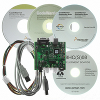
BOARD DEMO FOR 9S08 EL MCU
Manufacturer
Freescale Semiconductor
Type
MCUr
Datasheets
1.DEMO9S08EL32.pdf
(356 pages)
2.DEMO9S08EL32.pdf
(14 pages)
3.DEMO9S08EL32.pdf
(2 pages)
Specifications of DEMO9S08EL32
Contents
Evaluation Board
Processor To Be Evaluated
MC9S08EL32
Data Bus Width
8 bit
Interface Type
RS-232, USB
Operating Supply Voltage
12 V
Silicon Manufacturer
Freescale
Core Architecture
HCS08
Core Sub-architecture
HCS08
Silicon Core Number
MC9S08
Silicon Family Name
S08EL
Rohs Compliant
Yes
For Use With/related Products
MC9S08EL32
Lead Free Status / RoHS Status
Lead free / RoHS Compliant


The LIN 1.3 and earlier specifications transmit a checksum byte in the “CHECKSUM FIELD” of the LIN
message frame. This CHECKSUM FIELD contains the inverted modulo-256 sum over all data bytes. The
sum is calculated by an “ADD with Carry” where the carry bit of each addition is added to the least
significant bit (LSB) of its resulting sum. This guarantees security also for the MSBs of the data bytes. The
sum of modulo-256 sum over all data bytes and the checksum byte must be ‘0xFF’.
An optional checksum calculation can also be performed on a LIN data frame which is very similar to the
LIN 1.3 calculation, but with one important distinction. This enhanced calculation simply includes the
identifier field as the first value in the calculation, whereas the LIN 1.3 calculation begins with the least
significant byte of the data field (which is the first byte to be transmitted on the bus). This enhanced
calculation further ensures that the identifier field is correct and ties the identifier and data together under
a common calculation, ensuring greater reliability.
In the SLIC module, either checksum calculation can be performed on any given message frame by simply
writing or clearing CHKMOD in SLCDLC, as desired, when the identifier for the message frame is
decoded. The appropriate calculation for each message frame should be decided at system design time and
documented in the LIN description file, indicating to the user which calculation to use for a particular
identifier.
12.6.14 High-Speed LIN Operation
High-speed LIN operation does not necessarily require any reconfiguration of the SLIC module,
depending upon what maximum LIN bit rate is desired. Several factors affect the performance of the SLIC
module at LIN speeds higher than 20 kbps, all of which are functions of the speed of the SLIC clock and
the prescaler of the digital filter. The tightest constraint comes from the need to maintain ±1.5% accuracy
with the master node timing. This requires that the SLIC module be able to sample the incoming data
stream accurately enough to guarantee that accuracy.
allowable to maintain this accuracy.
220
Table 12-12. Maximum Theoretical LIN Bit Rates for High-Speed Operation
SLIC Clock
(MHz)
MC9S08EL32 Series and MC9S08SL16 Series Data Sheet, Rev. 3
20
18
16
14
12
10
8
6
4
2
Max LIN Speed w/ 1%
Accuracy (bps)
200,000
180,000
160,000
140,000
120,000
100,000
Table 12-12
80,000
60,000
40,000
20,000
Max LIN Speed w/ 1.5%
shows the maximum LIN bit rates
Accuracy (bps)
300,000
270,000
240,000
210,000
180,000
150,000
120,000
90,000
60,000
30,000
Freescale Semiconductor
1
Related parts for DEMO9S08EL32
Image
Part Number
Description
Manufacturer
Datasheet
Request
R

Part Number:
Description:
Manufacturer:
Freescale Semiconductor, Inc
Datasheet:
Part Number:
Description:
Manufacturer:
Freescale Semiconductor, Inc
Datasheet:
Part Number:
Description:
Manufacturer:
Freescale Semiconductor, Inc
Datasheet:
Part Number:
Description:
Manufacturer:
Freescale Semiconductor, Inc
Datasheet:
Part Number:
Description:
Manufacturer:
Freescale Semiconductor, Inc
Datasheet:
Part Number:
Description:
Manufacturer:
Freescale Semiconductor, Inc
Datasheet:
Part Number:
Description:
Manufacturer:
Freescale Semiconductor, Inc
Datasheet:
Part Number:
Description:
Manufacturer:
Freescale Semiconductor, Inc
Datasheet:
Part Number:
Description:
Manufacturer:
Freescale Semiconductor, Inc
Datasheet:
Part Number:
Description:
Manufacturer:
Freescale Semiconductor, Inc
Datasheet:
Part Number:
Description:
Manufacturer:
Freescale Semiconductor, Inc
Datasheet:
Part Number:
Description:
Manufacturer:
Freescale Semiconductor, Inc
Datasheet:
Part Number:
Description:
Manufacturer:
Freescale Semiconductor, Inc
Datasheet:
Part Number:
Description:
Manufacturer:
Freescale Semiconductor, Inc
Datasheet:
Part Number:
Description:
Manufacturer:
Freescale Semiconductor, Inc
Datasheet: